N93-582-01 Issue 1 NH Page 11 of 42 © Protec Fire Detection plc 2015
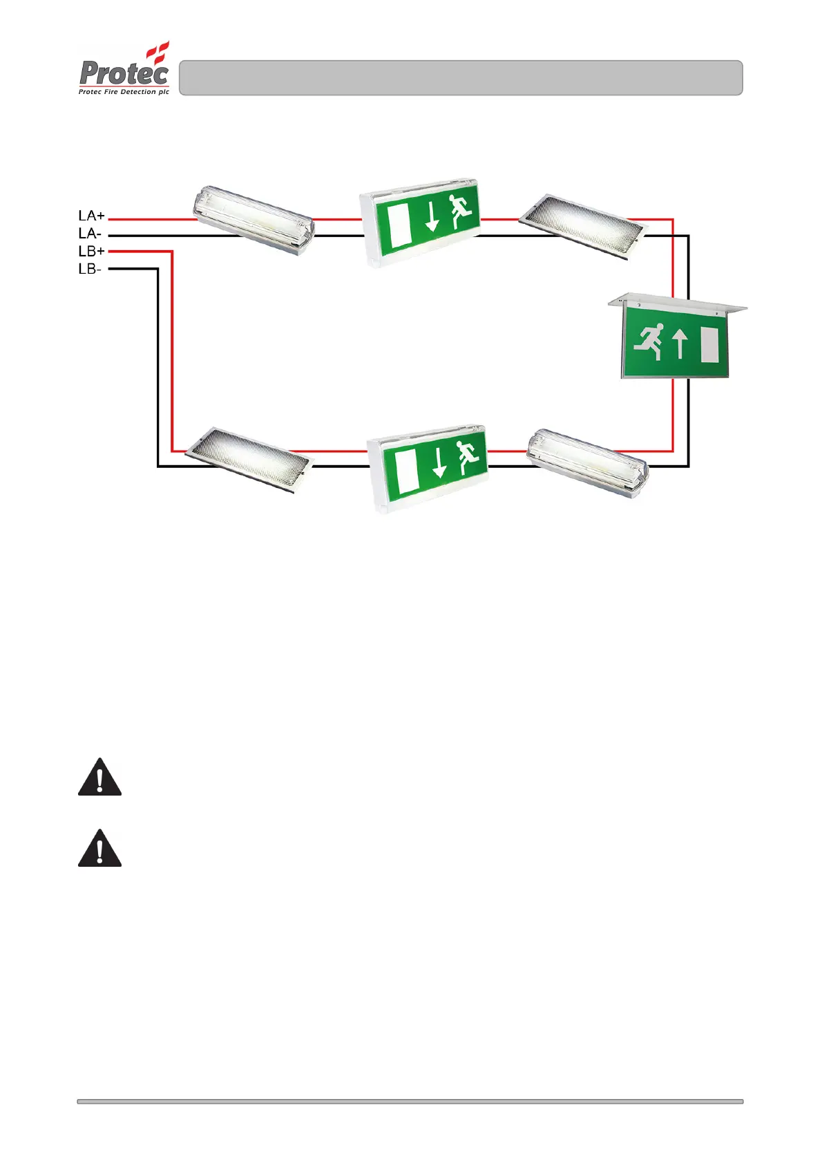
Figure 7.0 Typical Digilite® DL500 loop configuration
7.5 Network Interface Wiring
If the Digilite® DL500 installation is IP enabled a CAT5 cable terminated in a RJ45 plug must be
provided by the I.T management of the installation to their network. This cable plugs into the
corresponding socket on the TCP/IP network card mounted in the back-box of the Digilite® DL500.
8.0 Insulation Testing of Cabling Prior to Connection
Before connecting any external cables to any field device or the Digilite® DL500, tests should be carried out
using a 500V DC insulation tester ( ‘ Megger
® ‘
). If tests are performed the insulation readings between each
cable core, and each cable core and earth must be greater than 10MΩ.
The Digilite® DL500 or associated devices must not be connected to any cables when high
Voltage insulation tests are being performed on the cabling. The cabling must be completely
discharged prior to connection to the Digilite® DL500. Equipment connected to the cabling
during insulation tests will be damaged by the high voltages used, invalidating any warranty.
Do not test IP network cabling