N93-582-01 Issue 1 NH Page 24 of 42 © Protec Fire Detection plc 2015
10.6 Logging Loop Devices
Logging and mapping loop devices is the process the Digilite® DL500 uses to work out how many,
and what type of devices are connected to the loop.
Before logging always ensure there are no loop faults on the panel
The Digilite® DL500 WILL NOT run automatic tests during the logging phase
To allow the Digilite® DL500 to process logged devices they must be given a loop
address and all relevant programming data as required (see section 10.7).
Logging
During the logging phase all relevant devices connected to the loop are logged and stored in
memory ( devices will not be logged if the Digilite® DL500 does not support the device type, or the
software version of the device is not supported by the Digilite® DL500 ).
When the Digilite® DL500 has logged a loop device it searches the existing panel loop device data
to see if the loop device is already logged and allocated on the system, if it is, the software version
and LDR status of the loop device is updated in memory. By doing this, site files that have been
created using a device serial number barcode scanner ( which does not contain the device software
version or LDR data) and downloaded using the PC commissioning software are completed. The
resulting ‘complete’ site file must always be uploaded from the Digilite® DL500 to the PC and
stored for backup.
1. Enter the engineer code supplied with the system to access the menus.
2. Using the ◄ or ► keys scroll to the LOG LOOP DEVICES menu press the ↵
↵↵
↵ key to begin
the loop logging sequence ( as shown in figure 10.1 )
Line 1 of the display indicates the logging and mapping progress, and has the following sections.
RESETTING LOOP
Displayed when the Digilite® DL500 is resetting the loop to make sure all loop devices are ready to
be logged.
LOGGING LOOP
Displayed when the Digilite® DL500 is logging the loop devices.
LOGGING COMPLETE
Displayed when the Digilite® DL500 has completeds logging the loop devices. Logged device data is
now stored in temporary memory.
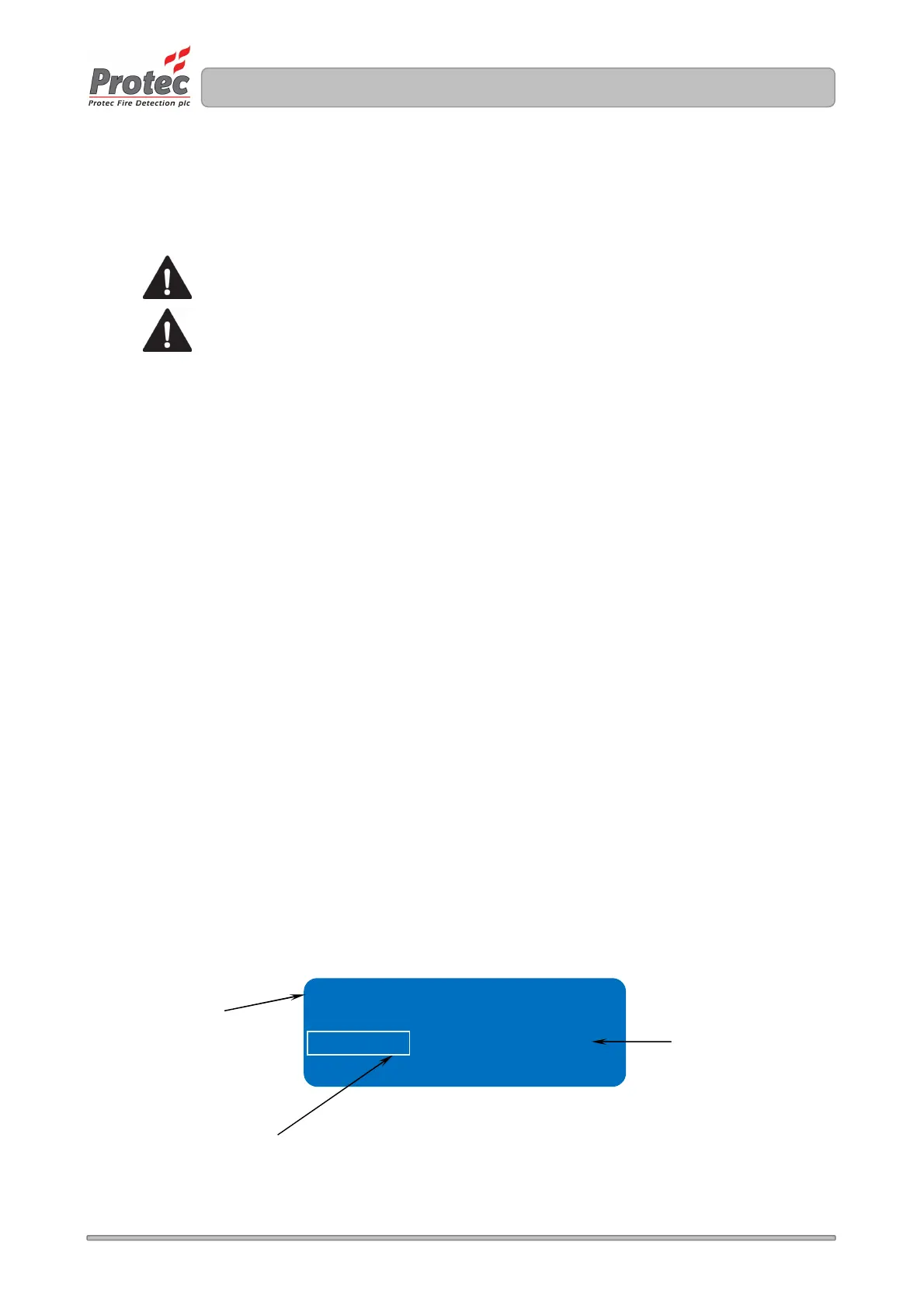
Figure 10.1 Digilite® DL500 loop logging display
Logging = 001 ( 000 )
This field indicates the number
of loop devices logged
This field indicates the change in
the number of logged devices
compared to those stored in the
panel
Row 1 displays the logging
process