N93-582-01 Issue 1 NH Page 19 of 42 © Protec Fire Detection plc 2015
9.10 Refitting the Control PCB Housing
Ensure that all cable earth connections are sleeved to insulate them and then securely connect them
to the brass earth terminals in the back-box.
Carefully route the battery leads ( from the rear of the control PCB housing ) down between the two
batteries.
Replace the Control PCB housing ( a reversal of removal ), ensuring it is pushed flush to the back
box and that the battery leads and TCP/IP data connection lead ( if fitted ) do not get trapped.
Secure with the four screws removed previously, taking care not to over tighten the screws.
9.11 Connecting the Addressable Loop Wiring
The Digilite® DL500 loop wiring must always be connected as a complete loop ( LA + and LA -
connections ) to each device, then back to the panel again ( LB + and LB - connections ). Please see
figure 9.7.
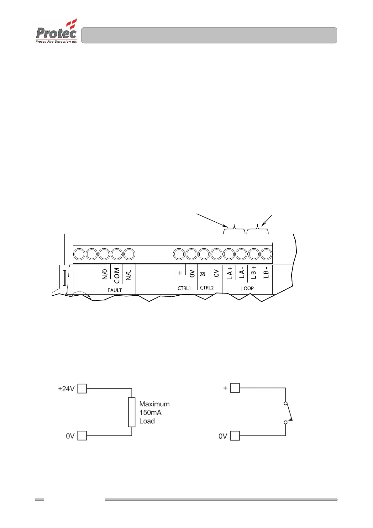
Figure 9.7 Loop Connection Details
9.12 Connecting the Auxiliary Wiring
The auxiliary wiring can now be connected if required. The auxiliary wiring comprises the control
inputs, auxiliary 24V supply output, and global fault contacts. Note that these connections are
optional and if not used do not require any termination.
Figure 9.8 Auxiliary 24V Output and Control Input Details
Auxiliary 24V Output Control 1 and 2 Input
Outgoing loop connections
Return loop connections