N93-582-01 Issue 1 NH Page 31 of 42 © Protec Fire Detection plc 2015
10.15 Displaying Panel Diagnostic Data
The DISPLAY DIAGNOSTIC DATA menu allows the engineer to view various values used within the
panel, and can be used as an aid when diagnosing problems.
1. Enter the engineer code supplied with the system and press the ↵
↵↵
↵ key to access the menus.
2. Using the ◄ and ► keys navigate to the DISPLAY DIAGNOSTICS DATA menu screen and
press the ↵
↵↵
↵ key to accept the option.
The screens show salient operating parameters of the panel, see figures 10.13 and 10.14
3. Using the ◄ and ► keys scroll round the sub screens as shown below.
4. Press the Back or Escape keys in any screen to return to the main menu.
.
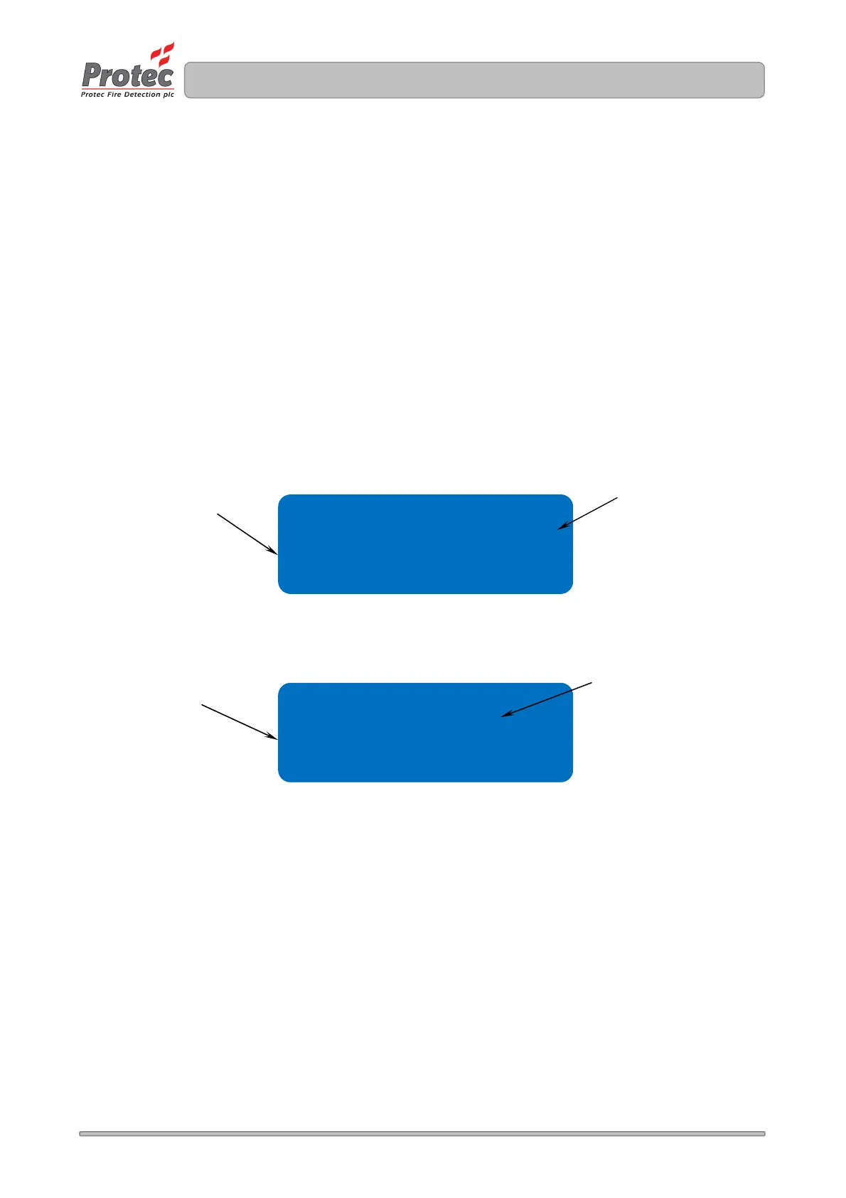
Figure 10.13 Diagnostic data screen 1- PSU DATA
Figure 10.14 Diagnostic data screen 1 - AUXILIARY DATA
Aux 24v = OK ( 861)
loop ol val = 405
Chg volts = 27.4v
Batt volts = 27.0v
Indicates the battery
charger Voltage
Internal loop driver
values
Indicates the standby
battery Voltage
Indicates the state of the Auxiliary
24V output.
OK is normal
SC means short circuit fault