N93-582-01 Issue 1 NH Page 14 of 42 © Protec Fire Detection plc 2015
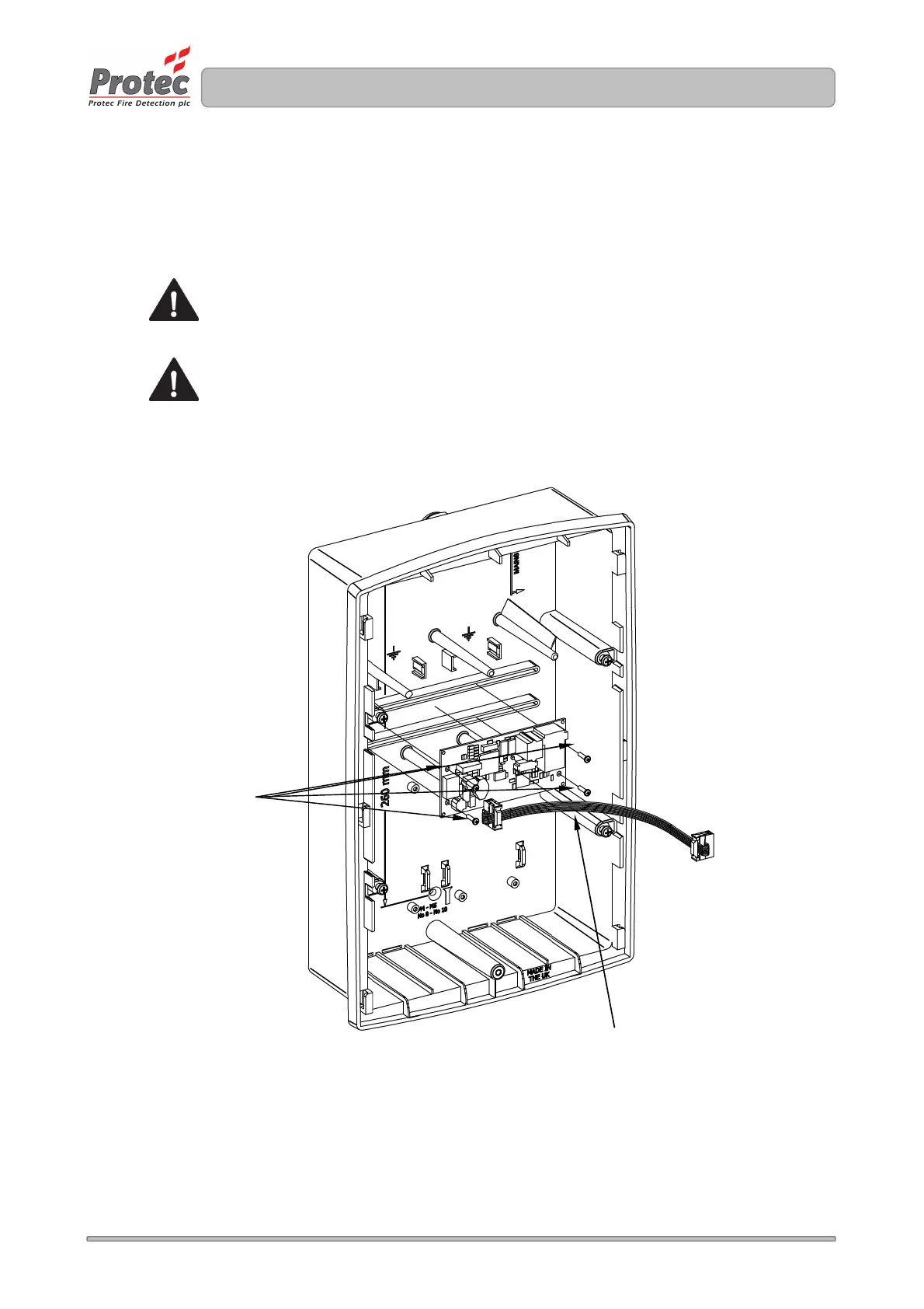
9.4 Removal of the optional TCP/IP Interface PCB and Data Cable
If the installation includes the Digilite® DL500 TCP/IP interface card, this must be removed
from the rear of the back-box. With reference to Figure 9.2.
Carefully remove the TCP/IP board by unscrewing and removing the four screws (one at each corner
of the PCB).
Do not touch any components on the PCB.
Store the TCP/IP Interface PCB, Data cable and Screws in a safe dry place for use
later.
Figure 9.2 Removal of the (optional) TCP/IP Interface Card and Data Cable
Screws
Data connection cable
to main panel