N93-582-01 Issue 1 NH Page 32 of 42 © Protec Fire Detection plc 2015
IPA 000.000.000.000
SNM 000.000.000.000
GWA 000.000.000.000
NODE 001
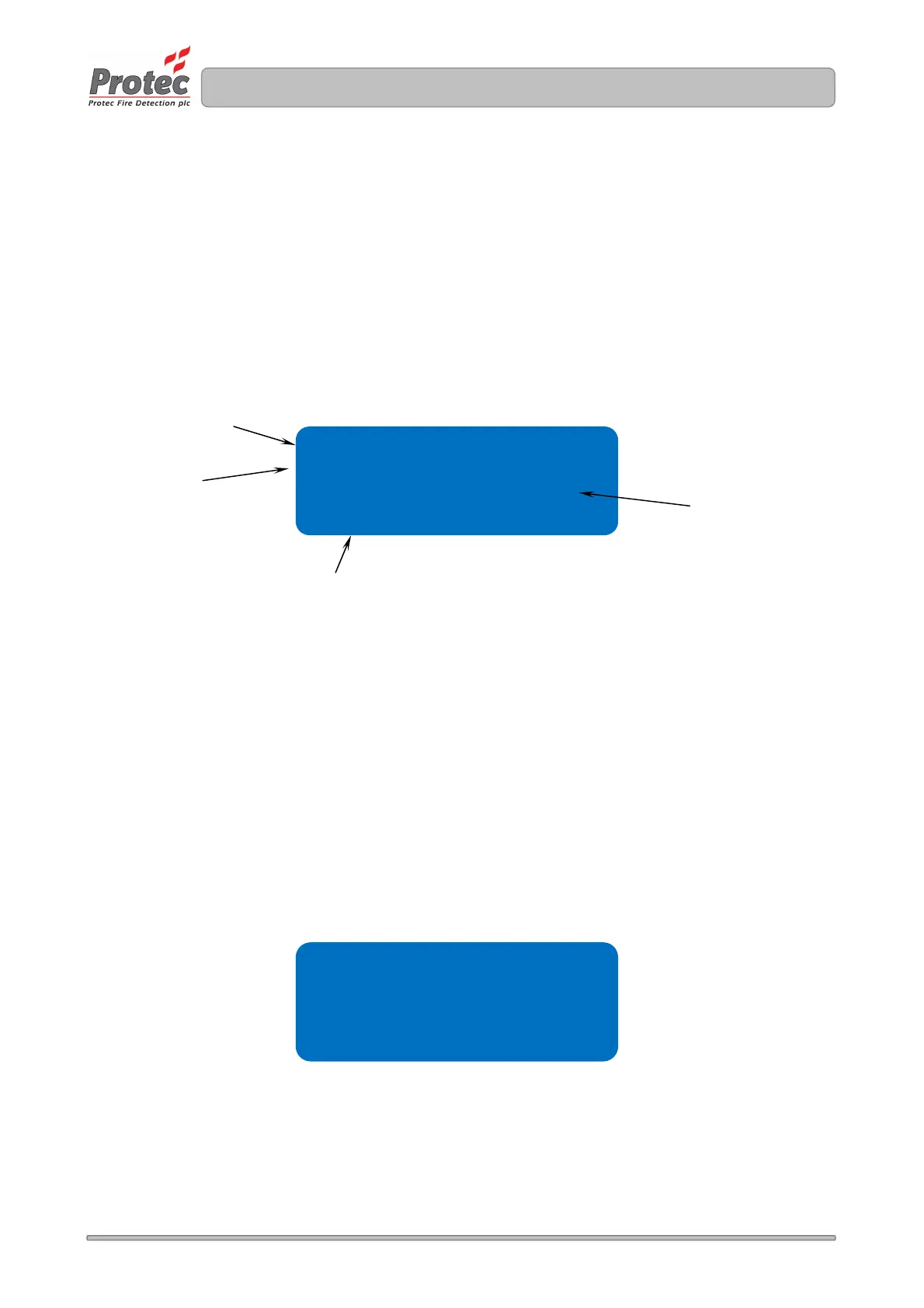
10.16 Displaying Panel Manufacturing Details
The DISPLAY PANEL DETAILS menu function allows the engineer to view the manufacturing details
of the panel, which include software versions, panel serial number and the revision of the site file.
1. Enter the engineer code supplied with the system and press the ↵
↵↵
↵ key to access the menus.
2. Using the ◄ and ► keys navigate to the DISPLAY PANEL DETAILS menu screen and press
the ↵
↵↵
↵ key to accept the option.
4. Press the Back or Escape keys in any screen to return to the main menus.
Figure 10.16 Display Panel Data display
10.17 Displaying the Programmed Network Configuration Settings
The DISPLAY NETWORK SETTINGS menu function allows the engineer to view the programmed IP
network settings of the panel, these comprise the IP address (IPA), Subnet Mask (SNM), Gateway
Address (GWA) and Node Number.
1. Enter the engineer code supplied with the system and press the ↵
↵↵
↵ key to access the menus.
2. Using the ◄ and ► keys navigate to the DISPLAY NETWORK SETTINGS menu screen and
press the ↵
↵↵
↵ key to accept the option.
4. Press the Back or Escape keys in any screen to return to the main menus.
Figure 10.17 IP Network Settings Screen
The revision of the
Site Data file format
The manufacturing
serial number of the
panel
Sw ver 1.01
Sp ver 0.00
snum D000100
sf rev 0001
The sub software
version
The main software
version of the
operating system