Chapter 2 System Configuration
PA-6225 SERIES USER MANUAL
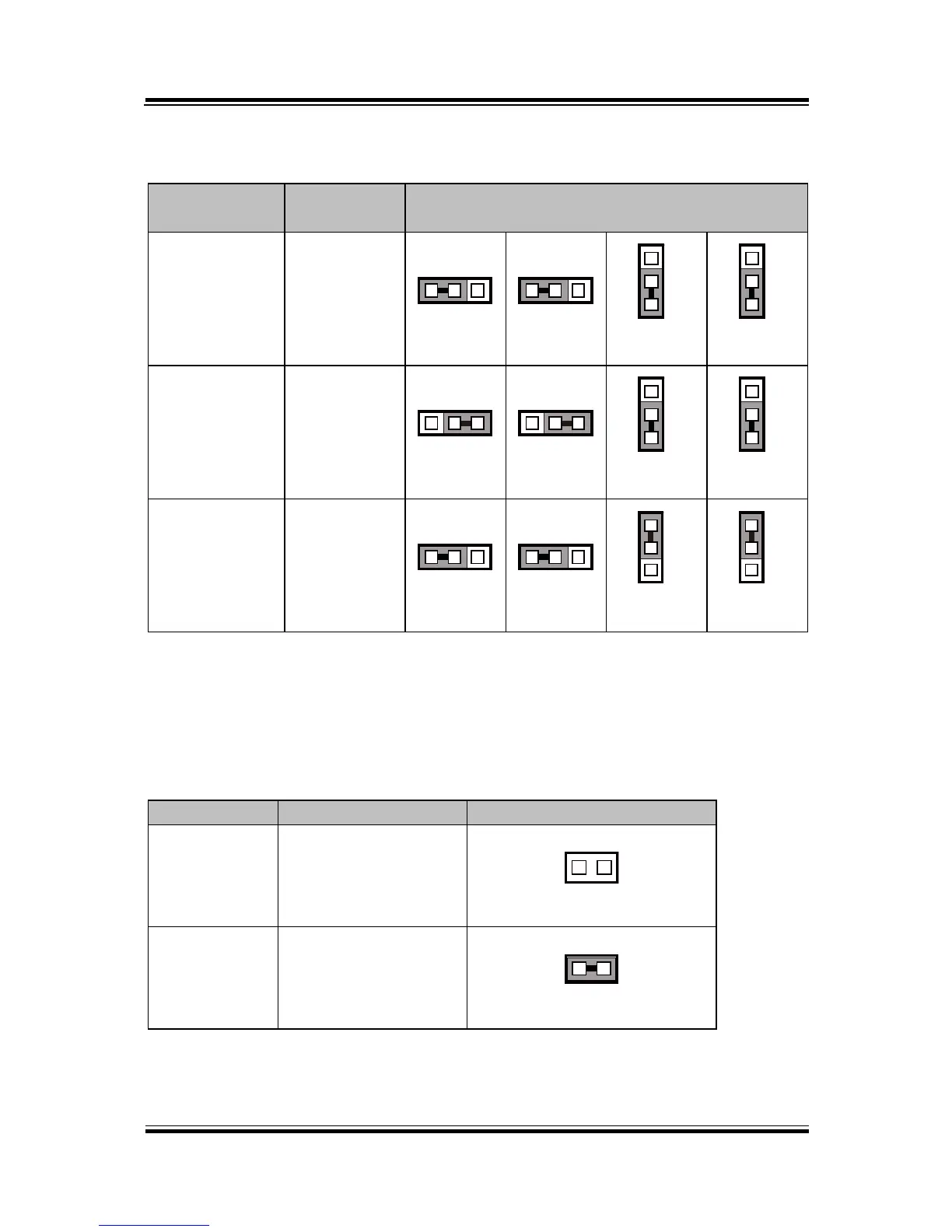
2-4-19. Touch Panel Signal Interface Selection
JP14, JP15, JP38, JP39: Control connectors for touch panel signal interface.
JP14: 1-2
JP15: 1-2
JP38: 2-3
JP39: 2-3
JP14: 2-3
JP15: 2-3
JP38: 2-3
JP39: 2-3
JP14: 1-2
JP15: 1-2
JP38: 1-2
JP39: 1-2
Notes: The COM2 & COM2_1 connectors will not function when JP38 & JP39 are set
as 1-2 connected.
2-4-20. Clear CMOS Data Selection
JP3: Clear CMOS data selection
Note: To clear CMOS data, you must power off the computer and set the jumper to
“Clear CMOS” as shown above. After five to six seconds, set the jumper back to
“Normal” and power on the computer.