DFM 6.1 INSTRUCTION MANUAL
40
POWER INPUT OPTION
9-32VDC
DFM 6.1 Flow Meters may be ordered factory-configured for 9-32VDC power input, or a 9-32VDC Power Input
card can be installed in the place of the 100-240VAC card in the field.
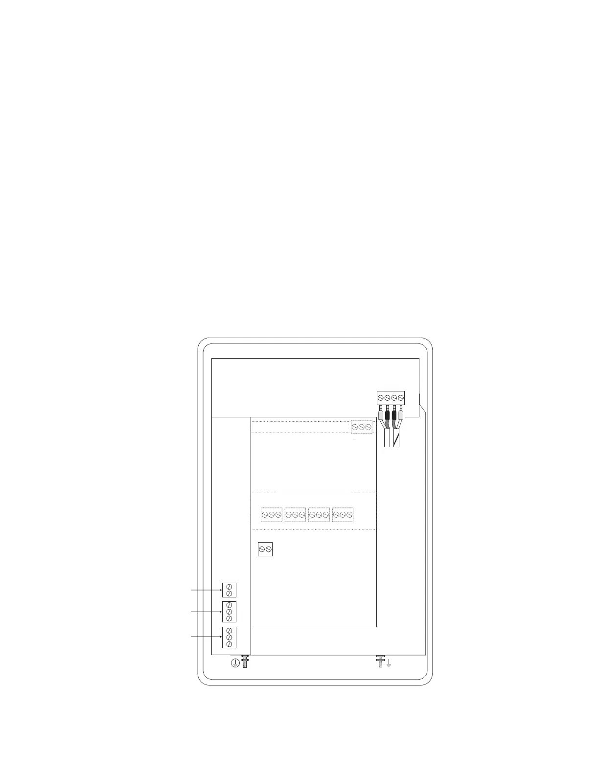
QUICK BENCH TEST:
Connect Sensor as shown below, then Power. Test operation of the DFM 6.1 by holding the sensor in one hand
and rubbing your thumb or fingers briskly across the face (plastic surface) of the sensor. Allow 15 seconds for the
DFM 6.1 to process the signal and display a flow value.
CONNECTIONS:
POWER INPUT: Connect 9-32VDC to the + and - terminals. The Power Input GND terminal must be connected to
the nearest Ground pole. A 1amp fuse in line is recommended.
DC
+ –
NO
C
NC
NO
C
NC
–
+
4-20mA
RLY2
RLY1
NC
C
NO
NC
C
NO
NC
C
NO
NC
C
NO
RLY3 RLY4 RLY5 RLY6
EXTRA RELAYS OPTION
SENSOR
GND
SERIAL COMMUNICATION OPTION
RS-485
Output
+ G
DC
GND
SENSOR
RCVR
GND
GND
TMTR
 Loading...