20
ENFORCER V11 PROGRAMMING GUIDE
CHANGE OUTPUTS
CHANGE OUTPUTS?
Endstation Outputs?
ZEM Outputs?
Wireless Bells?
Output Module Outputs?
Keypad Outputs?
Reader Outputs?
User Outputs?
This function programs all output types, Any output type may be programmed to any of the system outputs,
including any outputs for wireless bells. Wired outputs must be used within their rated capacity. Please see the
installation manual.
Common output types
For all output type options, please see “Appendix D - Output Types” on page 54. Most commonly used output
types are:
[0003] Intruder Any
[0018] Unconrmed Any
[0006] Conrmed Any
[0051] Line Fault
[0014] Siren Any
[0052] Mains Fail
[0016] Strobe Any
[1###] Follow Input
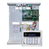
Endstation outputs
This function programs the wired bell, strobe and PGM output on the I/O board if connected.
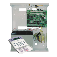
ZEM outputs
If a zone expander with additional outputs has been connected to the system, this function programs the outputs
on each expander. The address of the expander is required for programming the outputs.
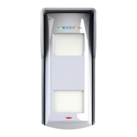
Wireless bells
At default, any wireless bells learnt to the system have the two outputs programmed as ‘Siren Any’ and ‘Strobe
Any’. These outputs can be programmed dierently if required.
Output module outputs
If an output expander is connected to the system, it must be addressed in this function. All output programming
is also done here. A maximum of 1 output expander can be connected to the system.
Keypad outputs
Allows the programming of the PGM options for the outputs located on the wired keypads.
Reader outputs
Allows the programming of the PGM options for the outputs located on the wired readers.
User outputs
These outputs are used for creating automation control for devices. The user can control them remotely from the
user menu on the keypad or via the smart device app. The automated user outputs can be programmed (either
latched or timed) along with a name for the output which will appear on the app or LCD screen.
Timed
A timed output will be active for a programmed period of time and then reset itself.
Latched
A latched output will stay active once triggered until it is manually reset.
Hint: Polarity of the PGMs. The polarity of the outputs are normally switched negative, i.e. normal status OFF = 12VDC and in active status ON = 0VDC.
 Loading...