GEM5000 Gas Analyzer
Page 46 of 102
For example:
If you do not have any suitable monitoring points you will need to drill (tap of ¾” BSP pipe
thread) a hole in the piping of between 25mm and 30mm in diameter to seat the conical
fitting on the anemometer (which is roughly between 20mm to 34mm). When not in use
the hole can be re-sealed with a ¾” BSP male bung.
Note: When the anemometer is not in use the conical fitting should be placed over
the probe to protect it.
The anemometer must fit centrally (the conical fitting must be set on the probe to half the
pipe ID before insertion). The arrow on the tip of the probe must point in the direction of
the gas flow.
Note: Use the thumb screw to help align the direction of the probe into the gas
stream.
Flow readings are most accurate when there is laminar flow (not turbulent). Turbulence
can be caused by a change in pipe direction or restriction. Ideally, upstream you want at
least 20 times the pipe ID along the length of the pipe without restriction or bend.
Downstream, you want at least five times the pipe ID along the length of the pipe i.e. for a
100mm ID you need 2000mm of clear pipe upstream, 500mm downstream.
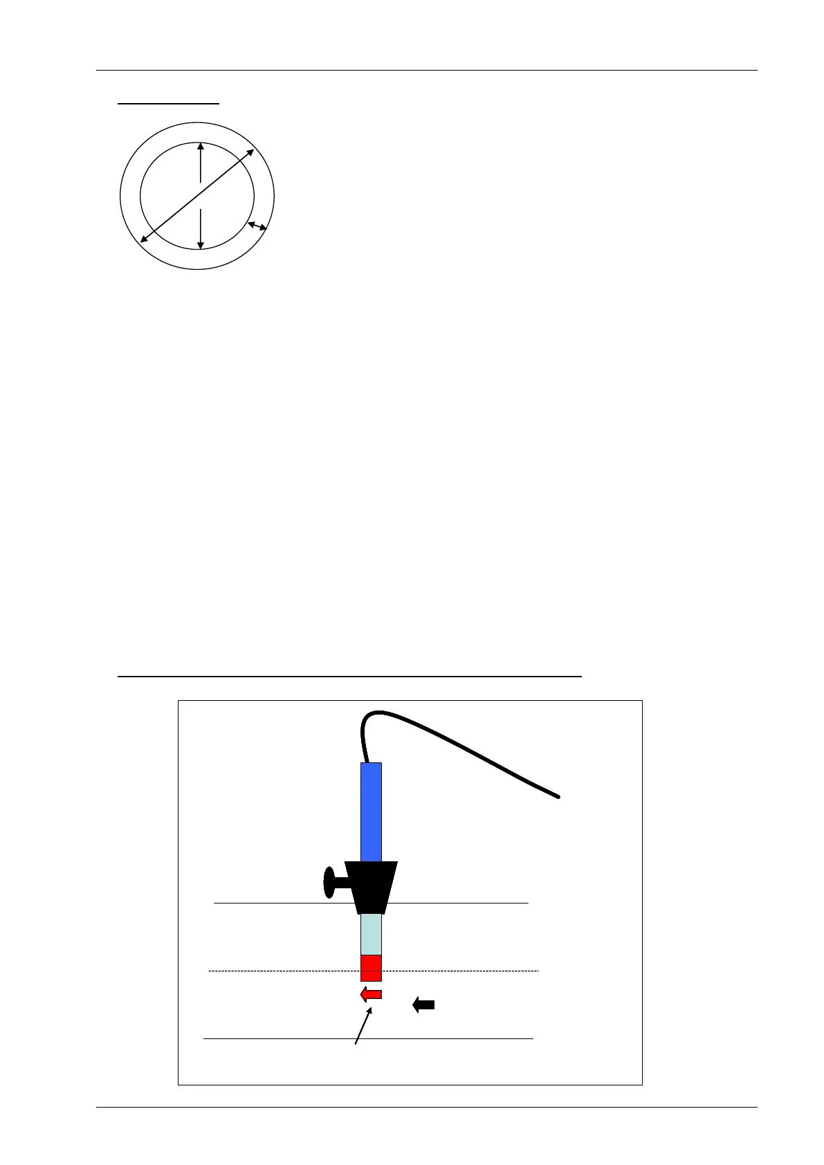
Example to show anemometer fitting into the sample point:
Pipe ID
Pipe OD
Wall Thickness
Conical Fitting
Pipe Centre Line
Pipe
Head
Flow Direction
Thumb Screw
Anemometer
Conical Fitting
Pipe Centre Line
Pipe
Head
Direction of the arrow must be in the same direction as the flow
Flow Direction
Thumb Screw
Anemometer
Conical Fitting
Pipe Centre Line
Pipe
Head
Flow Direction
Thumb Screw
Anemometer
Conical Fitting
Pipe Centre Line
Pipe
Head
Direction of the arrow must be in the same direction as the flow
Flow Direction
Thumb Screw
Anemometer