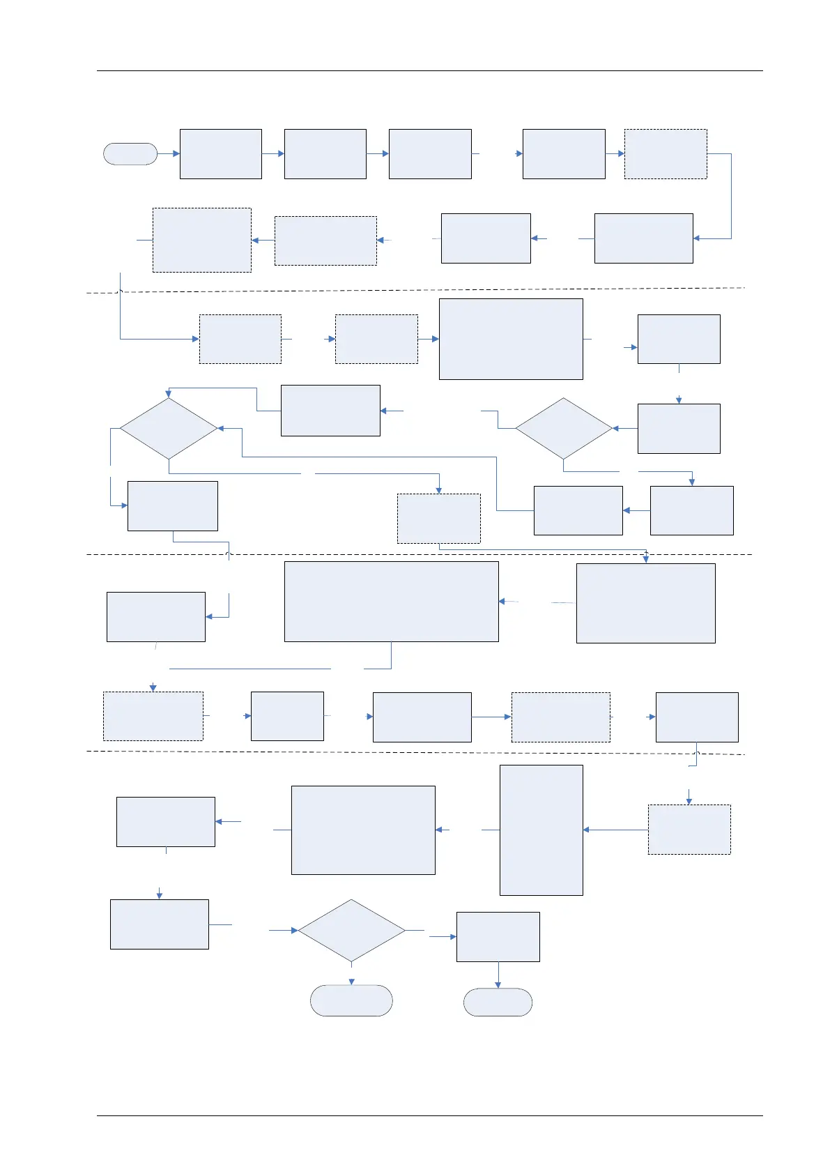
8.13 Taking gas and flow measurement
START
END
If using GAM
Set up GAM &
UPLOAD to
analyser
Air Purge
Instrument screen
Disconnect all tubing
and allow analyser to
purge with fresh air.
Select soft-key ‘Next’
If using GAM
Download
readings to GAM
Select
soft-key
‘Next’
GO TO select or
add borehole ID
YES
Zero Transducers
screen
Select Technician
ID if required or
soft-key ‘Skip’
Select
soft-key
‘Next ID’
Main Gas Read
Screen
Instrument
warm up
Disconnect all tubing from the
sample points and wait for
readings to stabilise. Select
soft-key ‘Next’ to continue
if readings return to zero,
otherwise to remove an offset
perform a zero
Connect the clear tubing to the static pressure
sample point. The blue tubing should be
connected to the differential pressure sample
point. The yellow exhaust tube must be vented to
atmosphere, a safe distance from the user.
DO NOT re-circulate back into the system.
Select
soft-key
‘Next’
Are you
using a
temperature
probe?
Wait for
Pump
to run
(i)
Attach
temperature
probe
Insert temperature
probe into the
sample point
Measure initial gas
flow reading displayed
in the Main Gas Read
Screen
Attach temperature
probe or key in
temperature manually
and press ‘Enter’
Adjusted Flow
Readings Fixed
NO Select soft-key
‘Temperature’
Take another
reading?
NO
Select
soft-key
‘Next’
Select or Add
Borehole Id and
press the ‘Enter’
key
If configured -
operator may locate
sample point using
GPS
Wait then
select
soft-key
‘Continue’
If required select soft-
key ‘Special Action’ to
update site & ID
question (ii)
Select
soft-key
‘Exit’
Main Gas Read
Screen
Gas Measurement
screen
Select
soft-key
‘Start’
Connect the clear sample tube to
the sample point. The yellow
exhaust tube should be vented a
safe distance from the user or
re-circulated back into the
system.
Wait for the initial
readings to
stabilise
Select
soft-key ‘Next’
Initial Gas
Readings Fixed
Select
soft-key
‘Next’
Select
soft-key
‘Next’
Wait for adjusted
readings to stabilise
on the Main Gas
Read Screen
System Pressure
Screen (iii)
Disconnect all
tubing from the
sample points and
wait for readings
to stabilise. Select
soft-key ‘Next’
if readings return
to zero, otherwise
to remove an
offset perform a
zero
Connect the clear sample tube to
the sample point. The yellow
exhaust hose should be vented a
safe distance from the sample
point or re-circulated back into
the system.
Pressure Readings
Fixed
Select
soft-key
‘Next’
Readings stored
successfully
Select
soft-key
‘Store’
Select
soft-key
‘Dismiss’
Wait for initial
readings to stabilise
on the Main Gas Read
Screen
Initial Flow
Readings Fixed
KEY:
(i) If GPS configured the first reading
will display a warning message. Select
soft-key ‘Dismiss’ to continue.
(ii) Special action – if required change
the analyser into GA mode of
operation.
(iii) System pressure reading only
available if set up on GAM.
NOTE: To restart a reading select soft-
key ‘Special Action’ followed by key 1
‘Restart Process’.
Are you
using an
anemometer?
Attach anemometer
& insert into the
sample point
YES
YES
NO
Select soft-key
‘System Pressure’
Select
Soft-key
‘Next’
Select
soft-key
‘Next’
Select
Soft-key
‘Next’
Taking a system pressure reading
Taking a flow reading
Taking a gas measurement reading
Select
soft-key
‘Next’
Input the temperature
on the Main Gas
Read Screen and
press the ‘Enter’ key