126 QXS G2 Hardware Installation and Maintenance Guide
Tabl e 1 8 provides companion data for Figure 103 relative to LED states for A/B/C SAS port expansion.
5U Chassis LEDs
This section provides information about the 5U chassis PSU LEDs, fan LEDs, Ops panel LEDs, drawer
LEDs, and DDIC LEDs.
NOTE: When the 5U84 chassis is powered on, all LEDs are lit for a short period to ensure they are
working. This behavior does not indicate a fault unless LEDs remain lit after several seconds.
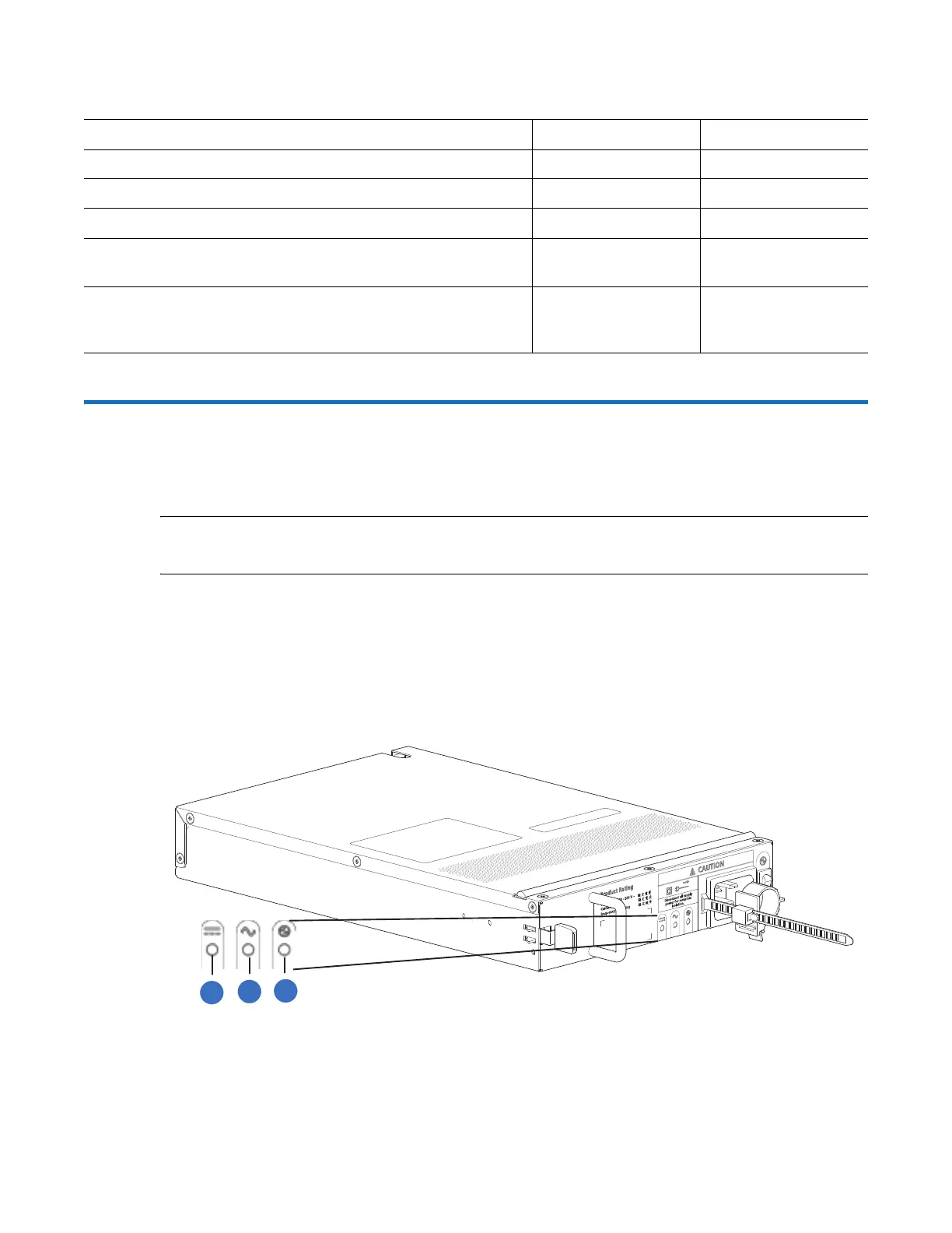
5U Chassis PSU LEDs
Under normal conditions, the PSU Power LEDs will be a constant green. Figure 104 provides an
illustration of the 5U chassis PSU LEDs. The RAID chassis and the expansion chassis uses the same
PSU. There are two PSUs in the RAID chassis and the expansion chassis.
Figure 104 PSU 5U84 CRU LEDs
Ta b l e 1 8 IOM LED Activity States
Condition Activity (Green) Fault (Amber)
No cable present Off Off
Cable present: all links up/no activity On Off
Cable present: all links up/with aggregate port activity Blinking Off
Critical fault: Any fault causing operation of the cable to cease
or fail to start (e.g., over current trip).
Off On
Non-critical fault: any fault that does not cause the connection
to cease operation (e.g., not all links are established; over
temperature).
Blinking Blinking: 1s on/1s off
1
PSU OK LED: Green
2
AC Fail LED: Amber/blinking amber
3
PSU Fail LED: Amber/blinking amber
1
2
3
 Loading...


