204 QXS G2 Hardware Installation and Maintenance Guide
b With your other hand, grasp the handle and pull the PSU outward (detail No.2). Supporting
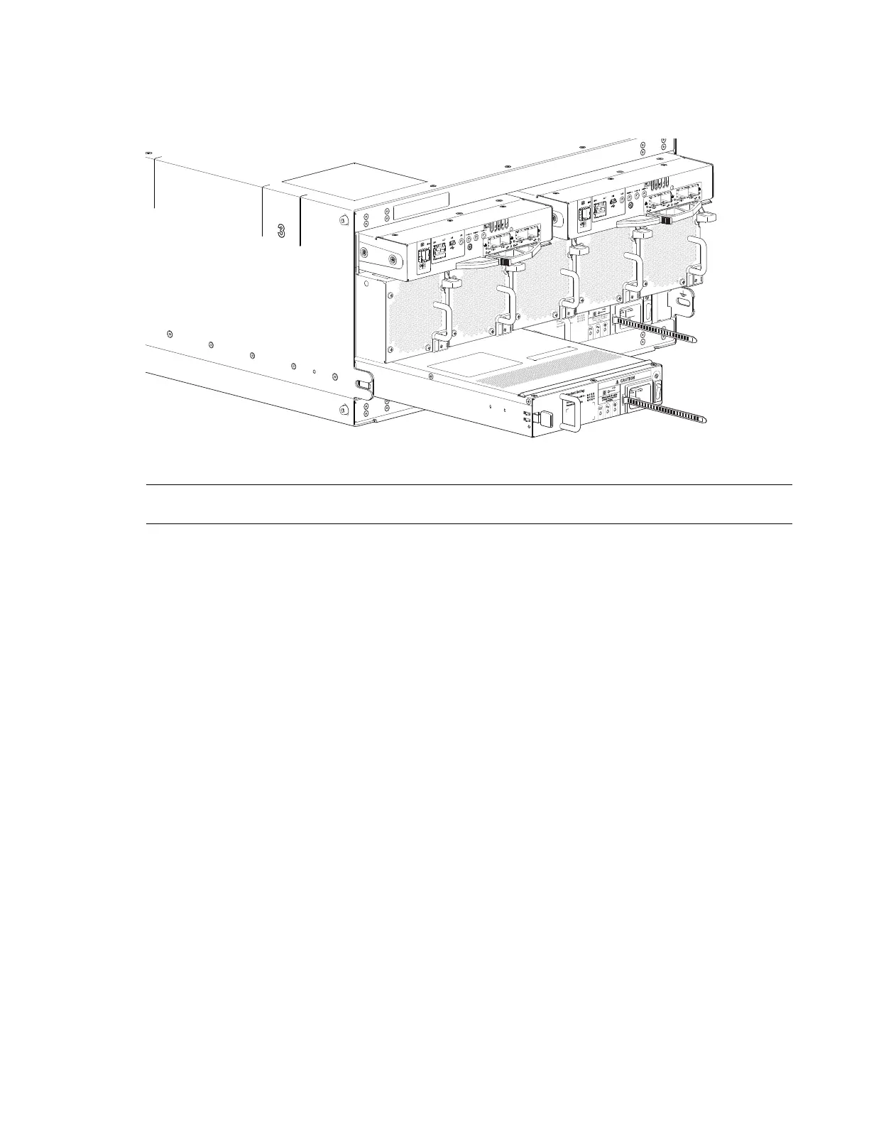
the PSU with both hands, remove it from the chassis. See also Figure 167.
Figure 167 Removing a PSU-2
8 If replacing both PSUs. repeat step 5 through step 7.
IMPORTANT: The PSU slot must not be empty for more than 2 minutes while the chassis is powered.
Installing a 5U84 System PSU
1 Ensure that the PSU is switched off.
If replacing both PSUs, the chassis must be powered off via an orderly shutdown using the
management interfaces.
2 Orient the PSU for insertion into the target slot on the chassis rear panel, as shown in Figure 167.
3 Slide the PSU into the slot until the latch clicks home.
4 Connect the AC power cord.
5 Move the PSU power switch to the On position.
6 Wait for the Power OK LED on the newly inserted PSU to illuminate green. See also Figure 165 on
page 203.
• If the Power OK LED does not illuminate, verify that the PSU is properly inserted and seated in
the slot.
• If properly seated, the module may be defective. Check the disk management utility (GUI) and
the event logs for more information.
• Using the management interfaces (the disk management utility (GUI) or CLI), determine if the
health of the new PSU is OK. Verify that the Power OK LED is green, and that the Ops panel
states show no amber module faults.
7 If replacing both PSUs, repeat step 1 through step 6.
 Loading...


