Section II - General Description
S3 Emergency stop button
1 Electric cabinet
VC Vacuum control valve
IC Inlet connection
BV Thermostatic bypass valve
DC Discharge connection
CE Cable entry
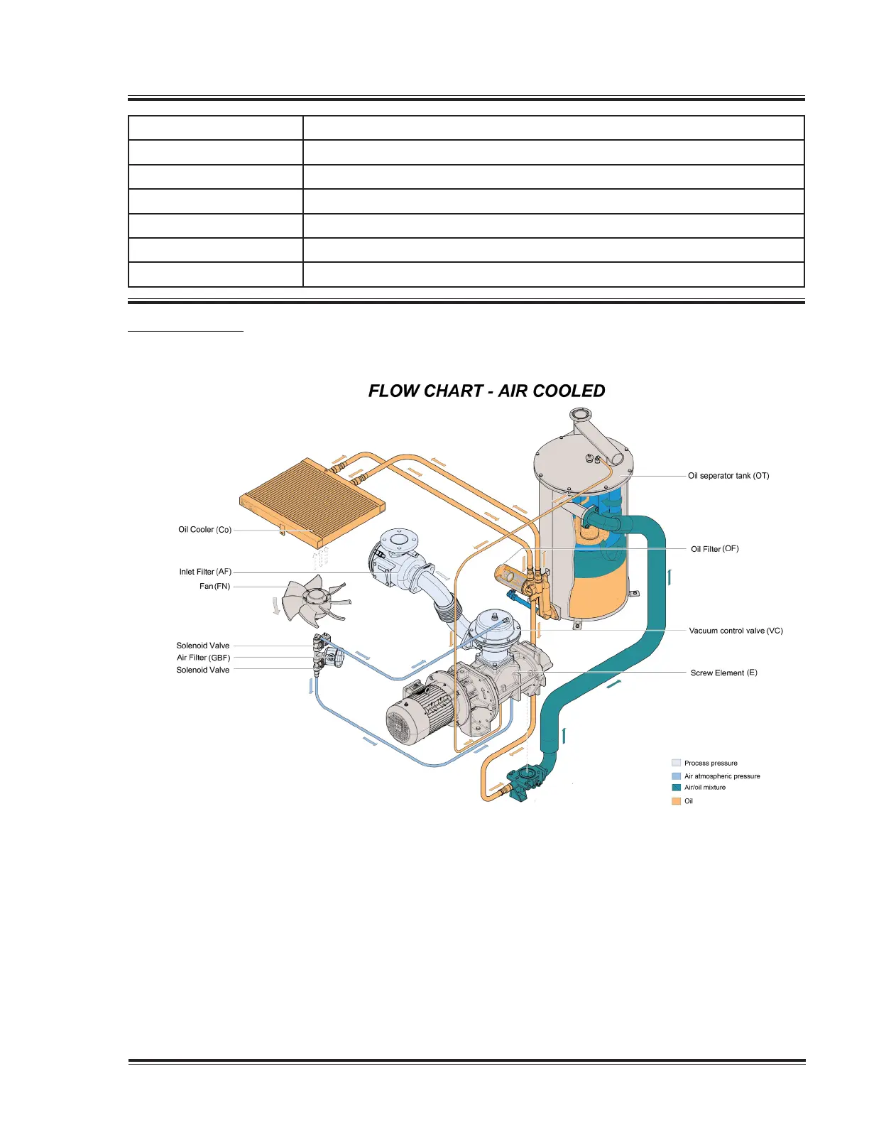
Flow diagram
Air ow
Air comes in through air intake filter (AF) and Vacuum Control Valve (VC) and is displaced
by the vacuum pump element (E).
A mixture of air and oil flows into the oil separator tank (OT).
After passing the air/oil separator filter, clean air, conditioned to a few parts per million, is
discharged through the outlet.
Oil system
Quincy Vacuum Pump-QSV Series 11
 Loading...