G2X Power and Tachometer Wiring
Power Connection
The G2X requires 12-18 volt DC power to operate properly. The power cable connects to the input
labeled PWR / TACH on the G2X unit. There are two different pigtails provided to allow for both
permanent power and tachometer connections to your vehicles electrical system or for quick connection
using the cigarette lighter adaptor. If you are using the three wire pigtail to connect the G2X directly to
your vehicles electrical system, make sure the connection provides a 2 – 5 amp fuse to protect against
short circuits. The cigarette lighter adaptor has an internal fuse, therefore no other short circuit
protection is required.
Tachometer Connection
The tachometer connection is optional and only provided on the three wire pigtail. However, when
properly connected and configured, the tachometer input will allow the G2X to display and/or record the
following data.
1. Engine RPM (Displayed on dash and recorded)
2. Gear indicator (Displayed on dash only)
The tachometer input requires a 5-18 volt, 50% duty cycle, square wave output signal. If your vehicle
does not have this type of tachometer output or you do not wish to display and record the above
information you may leave the yellow wire disconnected. The pinout of the three wire pigtail is as
follows:
Red wire – Switched 12-18 volt power
Yellow wire –tachometer input
Black wire – Chassis ground
!!! IMPORTANT WARNING !!!
DO NOT connect the yellow tachometer
input wire directly to any part of the ignition
coil. Doing so will result in damage to the
G2X tachometer input circuitry.
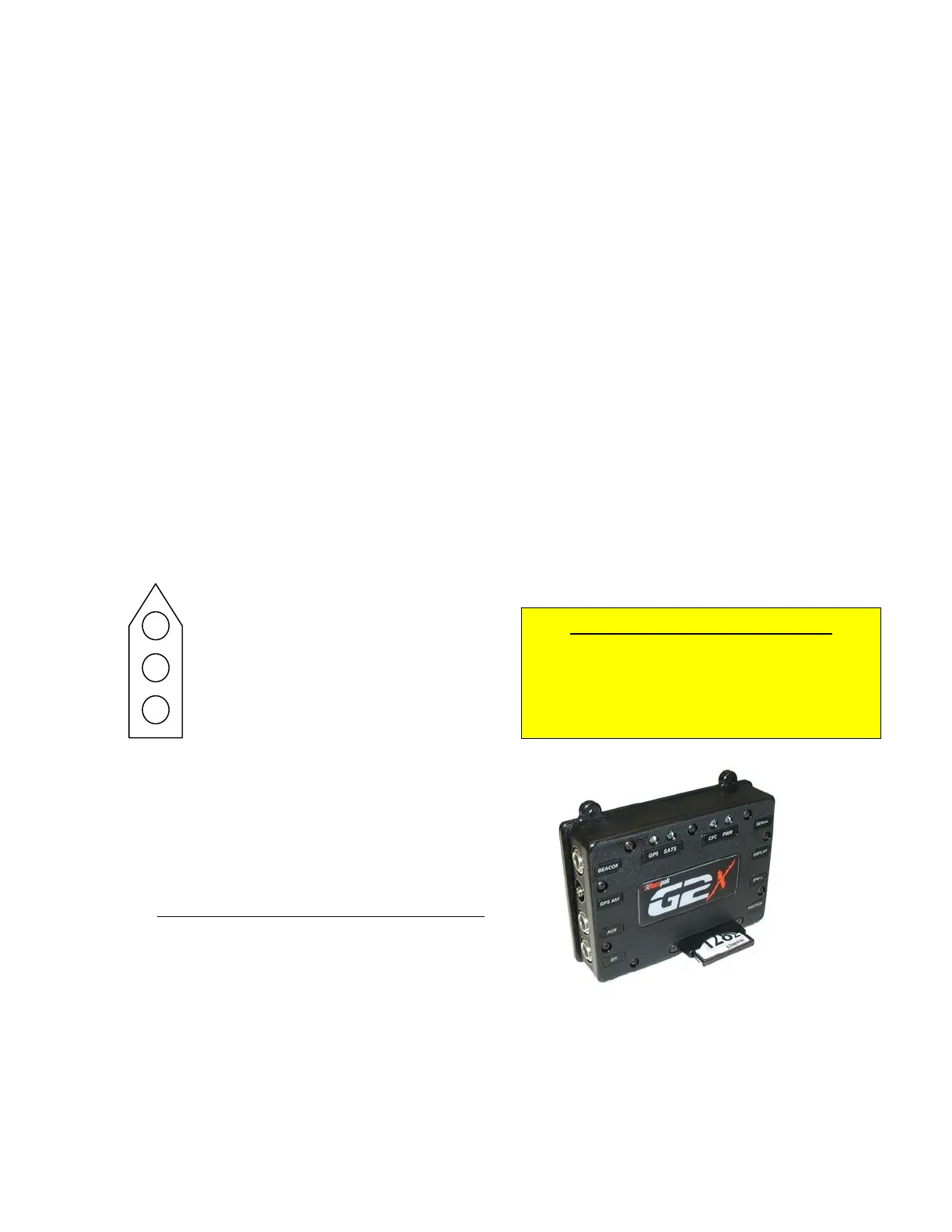
Compact Flash Card Installation
The compact flash memory card should be inserted in the
G2X with the manufacturers name facing toward the G2X
label. The card is fully inserted when the card is sitting
just below flush with the guide. If the card feels like it is
hanging up, gentle move it back and forth until it is fully
inserted.
Forcing the card may damage the connector.
Mounting the G2X Display Dash
The Display Dash is designed to mount utilizing three #10
mounting studs and screws. If the dash is mounted using a different method, insure it is properly
secured, to avoid the possibility of breaking free and becoming a projectile that could cause severe
injury to a person and/or your vehicle in the event of an accident or sudden stop. Connect the cable
from the Display Dash to the port labeled DISPLAY on the G2X unit.
12
 Loading...