1
st
Edition 3-1
3. Configuration and Installation
PMC Installation
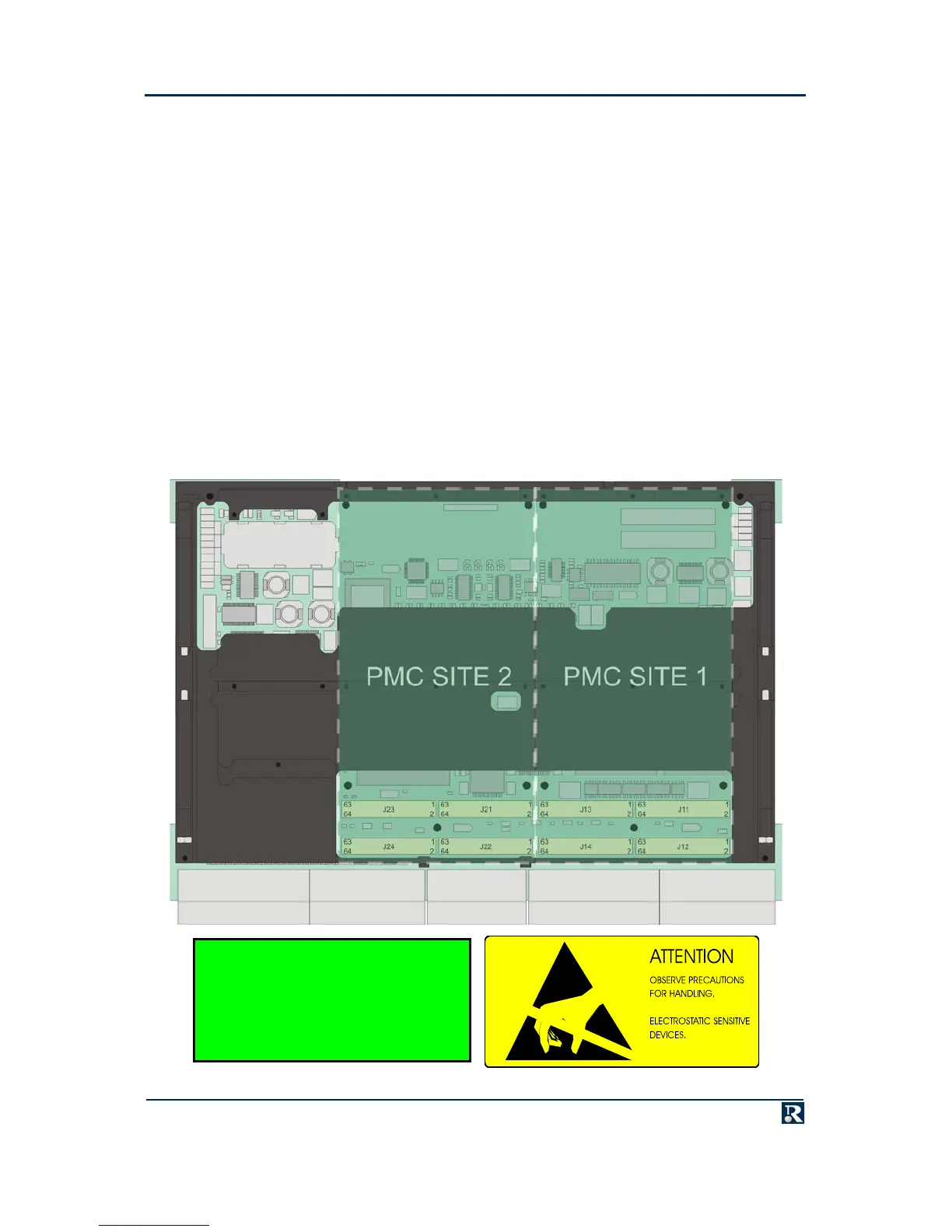
Two single width (or one double-width) PMCs may be fitted to the PowerPact6 processor. There are no
PMC keying pins, as the board can be user-configured for 5V or 3.3V signaling. Figure 3-1 shows the
positions of the PMC sites.
$
Note: PowerPact6 processors provide protection so that if a PMC card is fitted that shorts the +5 Volt rail to
the VIO supply, this is detected and the supply of 3.3 Volts to the VIO rail is inhibited. This protects
both the PowerPact6 processor and the PMC from burning up tracks or destroying parts.
Each PMC is supplied with a full kit of parts for mounting it, full fitting instructions and a manual. For
Radstone products, the PMC Installation Note, publication number HN4/3-99 contains the fitting
instructions. PMCs ordered with a PowerPact6 processor can be supplied factory fitted by Radstone, if
required.
It will usually be necessary to install driver software or implement other firmware configuration to
achieve full functionality of a PMC (see the specific PMC manual for the exact procedure).
Figure 3-1. PMC Position
£RECOMMENDATION
Where PMCs are not pre-installed,
prove PowerPact6 operation before
PMC installation.