1
st
Edition 5-12
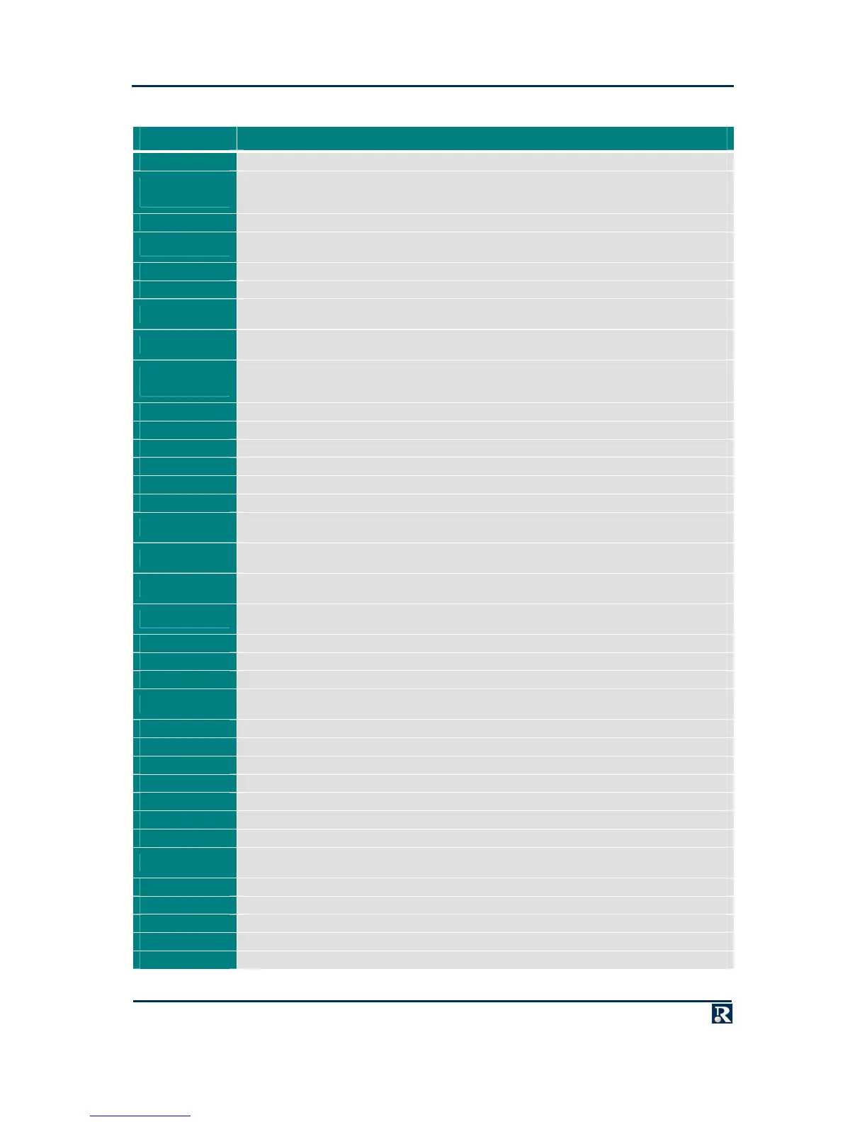
PCI/PMC Signal Descriptions
MNEMONIC DESCRIPTION
AD(0) to AD(63) Address/Data bits. Multiplexed address and data bus
CBE(0)~ to
CBE(7)~
Command/Byte Enables. During the address phase, these signals specify the type of cycle to carry
out on the PCI bus. During the data phase the signals are byte enables that specify the active bytes
on the bus
FRAME~ FRAME. Driven low by the current master to signal the start and duration of an access
DEVSEL~
Device Select. Driven low by a PCI agent to signal that it has decoded its address as the target of the
current access
PAR Parity. Parity protection bit for AD(0) to AD(31) and CBE(0)~ to CBE(3)~
IRDY~ Initiator Ready. Driven low by the initiator to signal its ability to complete the current data phase
LOCK~
LOCK. Driven low to indicate an atomic operation that may require multiple transactions to complete.
Pulled high by the PowerPact6 processor and not used
BUSMODE1
Bus Mode 1. When driven low by a PMC, this indicates that a PMC is fitted. The PMC presence can
be read from the PLD register
BUSMODE2~ to
BUSMODE4~
Bus mode. Driven by the host to indicate the bus mode. On the PowerPact6 processor this is always
PCI. BUSMODE2_1~ is pulled high by the PowerPact6 processor. BUSMODE3~ and BUSMODE4~
are pulled low by the PowerPact6 processor
HARDRESET~ Reset. Driven low to reset the PCI bus
TRDY~ Target Ready. Driven low by the current target to signal its ability to complete the current data phase
PERR~ Parity Error. Driven low by a PCI agent to signal a parity error
SERR~ System Error. Driven low by a PCI agent to signal a system error
STOP~ STOP. Driven low by a PCI target to signal a disconnect or target-abort
IRQW~ to IRQZ~ Interrupt lines. Level-sensitive, active-low interrupt requests
CLK0
66.667 or 33.333 MHz clock, according to M66EN. All PCI bus signals except HARDRESET~ are
synchronous to this clock
REQ_A/B~
Request. Driven low by a PCI agent (first [A] or second [B] device on PMC) to request ownership of
the PCI bus
GNT_A/B~
Grant. Driven low by the arbiter to grant PCI bus ownership to a PCI agent (first [A] or second [B]
device on PMC)
IDSEL_A/B
Initialization Device Select. First (A) or second (B) device on PMC chip select during configuration
cycles
REQ64~ Request 64 Bit. Driven low by a PCI master to request 64-bit transfer
ACK64~ Acknowledge 64 Bit. Driven low by PCI agent in response to REQ64
PAR64 Parity. Parity protection bit for AD(32) to AD(63) and CBE(4)~ to CBE(7)~
M66EN
66 MHz Operation. If this is left open by a PMC, PCI will operate at 66.667 MHz. If it is connected to
GND by a PMC, PCI will operate at 33.333 MHz
TCK Test Clock. Clock for the PMC JTAG
TMS Test Mode Select. Select Test Mode for PMC JTAG
TRST Test Reset. Reset any PMC JTAG devices
TDI Test Data In. Output data from the board JTAG chain
TDO Test Data Out. Input data to the board JTAG chain
3.3V +3.3V DC power
+5V +5V DC power
VIO
The supply rail for the PCI bus I/O voltage. For I/O signaling only, not main supply Can be linked for
+5V or +3.3V operation
EREADY Driven low by the PMC until it is ready to be enumerated
XCAP Determines PCI-X capability
-12V -12V DC power
+12V +12V DC power
GND Signal ground connection