1
st
Edition 3-2
Link Configuration
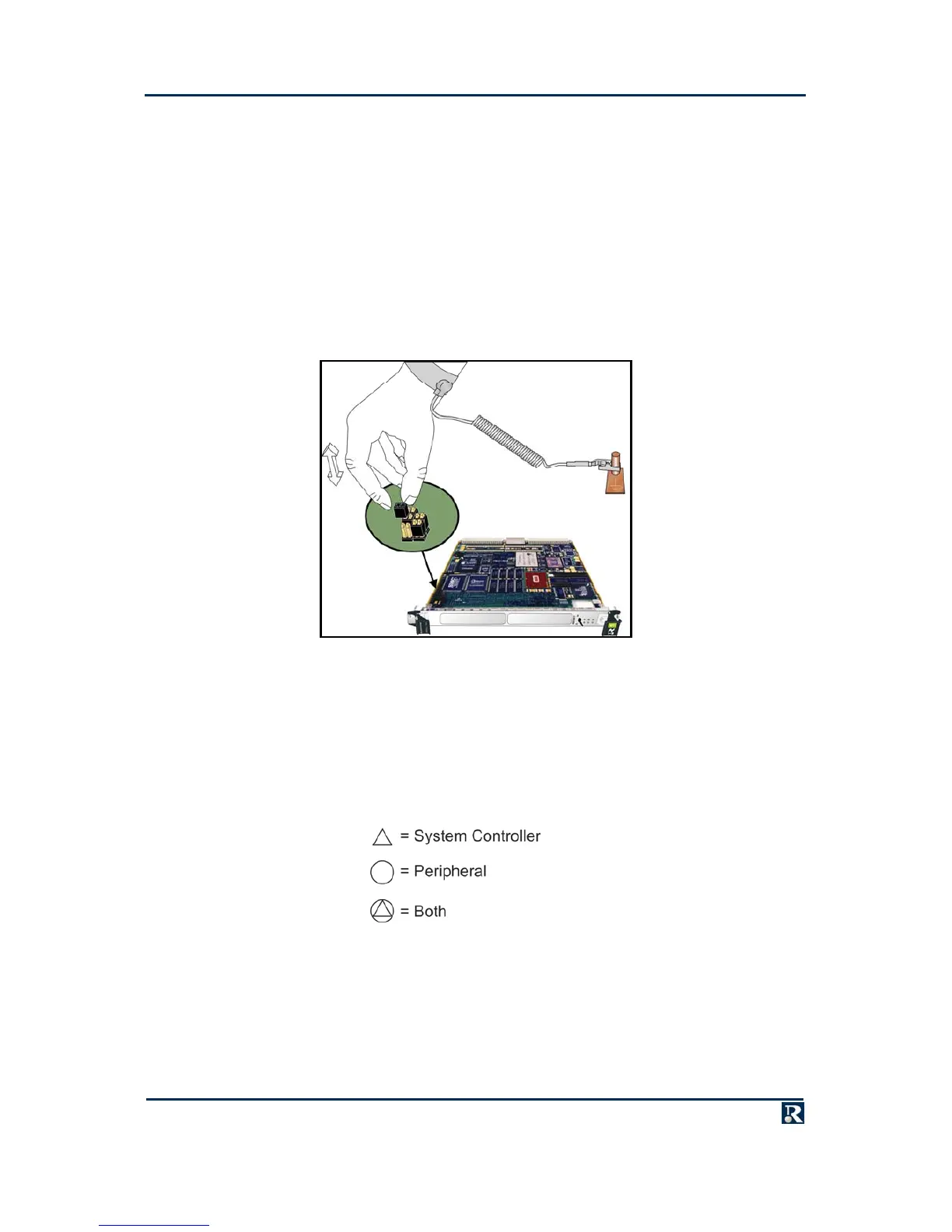
Board configuration is carried out by the insertion and removal of jumpers (configuration links). Where
these links are factory fitted, a default setting is used. For link ID, default and recommended settings,
refer to appropriate appendix, BSP, BIT and/or PPCBoot manual(s) - listed below.
Appendix A – CP1A
PPCBIT User Guide, Publication No. PPCBIT-0HU
PPCBoot Firmware User Manual, Publication No. PPCBOOT-0HL
LynxOS BSP Manual
VxWorks BSP Release Notes
All available manuals can be found via the Manuals CD-ROM.
Chassis Configuration
Unlike VME backplanes, the CompactPCI backplane does not use daisy chains for bus requests or
interrupt acknowledgements, so no configuration of the backplane is required before use.
However, the position of the PowerPact6 processor in the backplane determines whether it is System
Controller (providing CompactPCI clocks and arbitration) or a peripheral. If the PowerPact6 processor is
required to be System Controller, fit it in the dedicated System Controller slot. If the PowerPact6
processor is required to be a peripheral, it can be fitted in any slot except the System Controller slot. The
following symbols are used to indicate CompactPCI device capabilities:
The position of the PowerPact6 processor in the backplane also determines its Board ID using
geographical addressing.