1
st
Edition 5-15
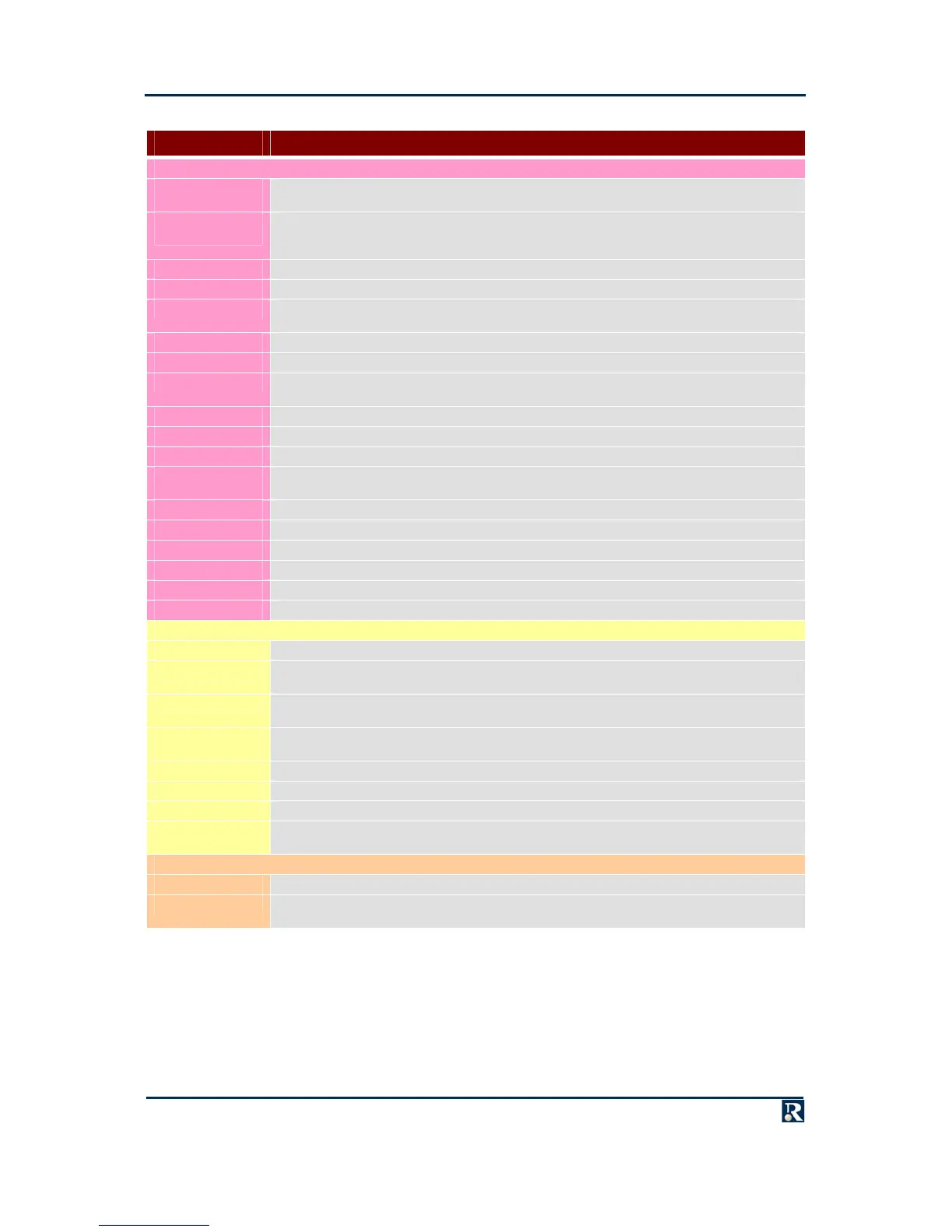
AFIX Signal Descriptions
MNEMONIC DESCRIPTION
PCI Bus
PCI_AD(0) to
PCI_AD(31)
Multiplexed address and data bus
PCI_CBE(0) to
PCI_CBE(3)
Command/Byte Enables. During the address phase, these signals specify the type of cycle to carry
out on the PCI bus. During the data phase the signals are byte enables that specify the active bytes
on the bus
PCI_PERR~ Parity Error. Driven low by a PCI agent to signal a parity error
PCI_SERR~ System Error. Driven low by a PCI agent to signal a system error
PCI_DEVSEL~ Device Select. Driven low by a PCI agent to signal that it has decoded its address as the target of
the current access
PCI_LOCK~ Lock. Driven low to indicate an atomic operation that may require multiple transactions to complete
PCI_FRAME~ Frame. Driven low by the current master to signal the start and duration of an access
PCI_TRDY~ Target Ready. Driven low by the current target to signal its ability to complete the current data
phase
PCI_IRDY~ Initiator Ready. Driven low by the initiator to signal its ability to complete the current data phase
PCI_STOP~ Stop. Driven low by a PCI target to signal a disconnect or target-abort
PCI_PAR Parity. Parity protection bit for AD0 to AD31 and BE0 to BE3
IRQW~, IRQX~,
IRQY~, IRQZ~
PCI interrupts
REQ0~ to REQ3~ PCI bus request by (up to 4) devices on the AFIX module
GNT0~ to GNT3~ PCI bus grant to (up to 4) devices on the AFIX module
CLK1 to CLK4 PCI clocks to (up to 4) devices on the AFIX module
RESET~ PCI reset signal generated by the host card
IDSEL1 to IDSEL4 Chip Select for PCI Configuration accesses to (up to 4) devices on the AFIX module
EREADY Enumeration Ready. Driven low by the AFIX module until it is ready for PCI enumeration
AFIX Control and Data
CARD_FITTED~ Connected to Signal Ground on the AFIX module to indicate presence of the card
IO(7:0) These signals should be pulled high on the host card and are tied low on the AFIX module to
indicate the Card Identifier
ISA_IO_FIT~ Connected to Signal Ground on the AFIX module when configured for basic I/O, to indicate to the
host that I/O is being routed to the backplane
PLD_DATA(0) to
PLD_DATA(3)
Control data to the AFIX module
ALEN Address Latch Enable
IOR~ I/O Read strobe
IOW~ I/O Write strobe
I2C_CLK,
I2C_DATA
System I
2
C bus
AFIX I/O
AFIX I/O See the individual AFIX modules for definitions of these pins
HDO_H/Jnn These pins may also be used for AFIX I/O (see the individual AFIX modules for definitions). If used
by the AFIX module, then they route to the J5 connector