1
st
Edition 3-4
Observing all antistatic and handling precautions, carry out the following installation procedure:
1) Insert the processor into the required slot of the CompactPCI rack or enclosure.
$ Notes:
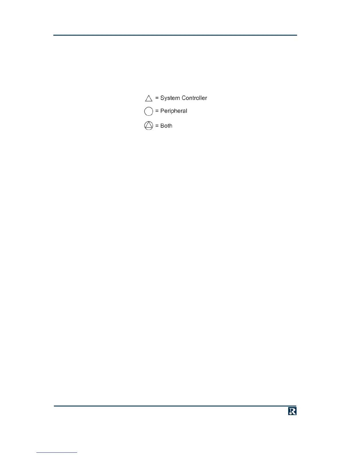
a. If the PowerPact6 processor is required to be System Controller (providing CompactPCI
clocks and arbitration), fit it in the dedicated System Controller slot. If the PowerPact6
processor is required to be a Peripheral, it can be fitted in any slot except the System
Controller slot. The following symbols indicate CompactPCI device capability:
b. The position of the PowerPact6 processor in the backplane also determines its board ID using
geographical addressing.
2) Push the board firmly home to ensure that backplane connectors mate correctly.
3) For air-cooled boards, tighten the captive screws at the top and bottom of the front panel to secure
the board in position.
$
Note: Pulling on any front panel cable connections could inadvertently disconnect the board
if it is not secured.
4) For conduction-cooled boards, tighten the
3
/
32
” (2.38 mm) hexagon-head screw-driven wedgelocks
at the top and bottom of the board to secure it in position and ensure a correct mechanical/thermal
interface. Use a calibrated torque wrench set to between 0.6 and 0.8 Nm.
5) To ensure optimum EMC performance, maintain ground continuity when taking I/O connections
from the front/rear panel connectors, or when the board is operating on a bus extender card.
Your PowerPact6 processor should now be installed into a CompactPCI rack or enclosure.