Instrument Tour
R&S
®
SMW200A
45Getting Started 1412.9220.02 ─ 21
See also "Analog I/Q Output Settings" in the user manual.
ADV DATA/CTRL
Option: R&S SMW-B9/-B13XT and R&S SMW-K503/-K504
Interface for exchanging of external data and control signals.
See user manual R&S SMW-K501/-K502/-K503/-K504 Extended and Real-Time
Sequencing, Real-Time Control Interface.
ADV TRIG, ADV CLK
Option: R&S SMW-B9/-B13XT
Input and output for synchronization signal in multi-instrument setups.
See also "Multi-Instrument Setups" in the user manual.
HS DIG I/Q
Option: R&S SMW-B9/-B13XT
Connectors for the input/output of high-speed digital I/Q signals, for example,
from and to Rohde & Schwarz instruments.
The interfaces require the options listed in Table 5-12.
For more information, see data sheet.
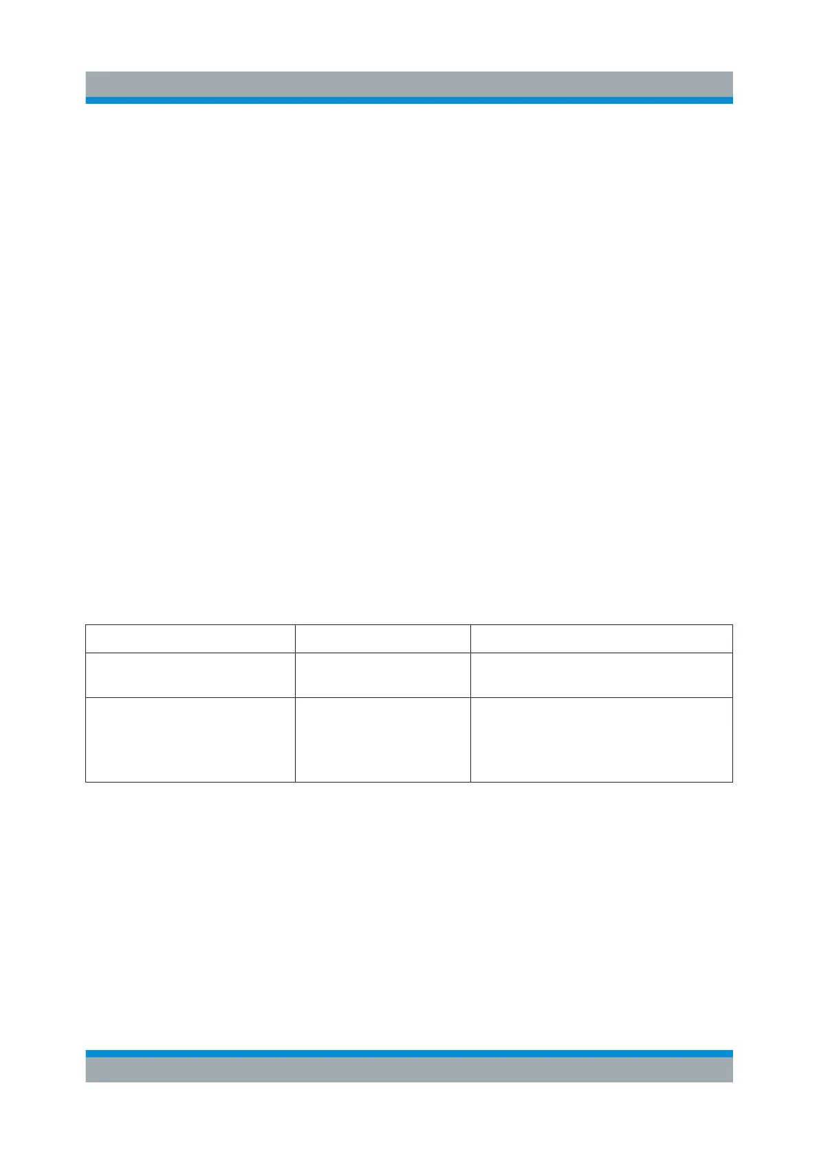
Table 5-12: Overview of the HS DIG I/Q interfaces and the required options
Location of the interface Designation Required option
CODER board CODER 1/2 In R&S SMW-B9, wideband baseband
generator
BBMM board BBMM 1/2 Out R&S SMW-B13XT, wideband base-
band main module
R&S SMW-K19 for the output of digi-
tal signals
The interface is a QSFP+ (Quad Small Form-factor Pluggable) module. It sup-
ports max. bandwidth of up to 50 Gsample/s with optical active cables.
A QSFP+ socket on the instrument has two components: a QSFP+ connector and
a QSFP+ cage. The QSFP+ cable is equipped with the QSFP+ plug.
Rear Panel Tour

 Loading...
