Chap t e r 6 : I ns t al l at i on
47
Cha p t e r 6: I nst a l l a t i o n
6.1 Planning the installation
This chapter explains how to install and connect the following:
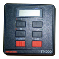
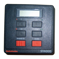
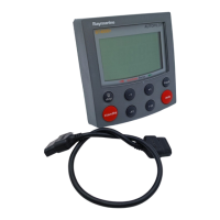
ïControl head
ïFluxgate compass
ïRudder reference transducer (optional)
ïWheel drive actuator (wheel pilots only)
ïTiller actuator (tiller pilots only)
ïNMEA interface
Before starting the installation, decide how you will site the units and
run the cables.
EM C i n st a l l a t i o n g ui d e l i ne s
All Raytheon equipment and accessories are designed to the best
industry standards for use in the leisure marine environment.
Their design and manufacture conforms to the appropriate
Electromagnetic Compatibility (EMC) standards, but correct
installation is required to ensure that performance is not compromised.
Although every effort has been taken to ensure that they will perform
under all conditions, it is important to understand what factors could
affect the operation of the product.
To minimise the risk of operating problems, all Raytheon equipment
and cables connected to it should be;
ïAt least 1 m (3 ft) from any equipment transmitting or cables
carrying radio signals e.g. VHF radios, cables and antennas. In the
case of SSB radios, the distance should be increased to 2m (7ft).
ïMore than 2 m (7ft) from the path of a radar beam. A radar beam
can normally be assumed to spread 20 degrees above and below the
radiating element.
ïThe equipment should be supplied from a different battery than the
one used for engine start. Voltage drops below 10 V in the power
supply to our products can cause the equipment to reset. This will
not damage the equipment, but will cause the loss of some
information and can change the operating mode.
 Loading...