Instruction Manual TR-Mark III 250V Version 1.10 Preliminary Page 10 of 57
4.2 Connection to Test Object
4.2.1 Hooking up a transformer
This section describes a typical, step by step operation of the TR-Mark III 250V.
Plug the TR-Mark III 250V into an available grounded outlet with 100/250 vac 50/60 Hz
power source.
Connect the TR-Mark III 250V to the transformer under test with the coloured test leads and
if required, use the Red 10 meter measuring lead extensions. The extensions will connect
into the multicolour leads. Check the nameplate information of the transformer. If the
nameplate is missing, it is still possible to test the transformer by a trial and error method.
The TR-Mark III 250V test set is designed to detect errors in transformer hook ups. Contact
the Raytech Service & Support department if you need assistance.
NOTE
No extra external leads or jumpers are required when using the
TR-Mark III 250V. All necessary connections are made internally.
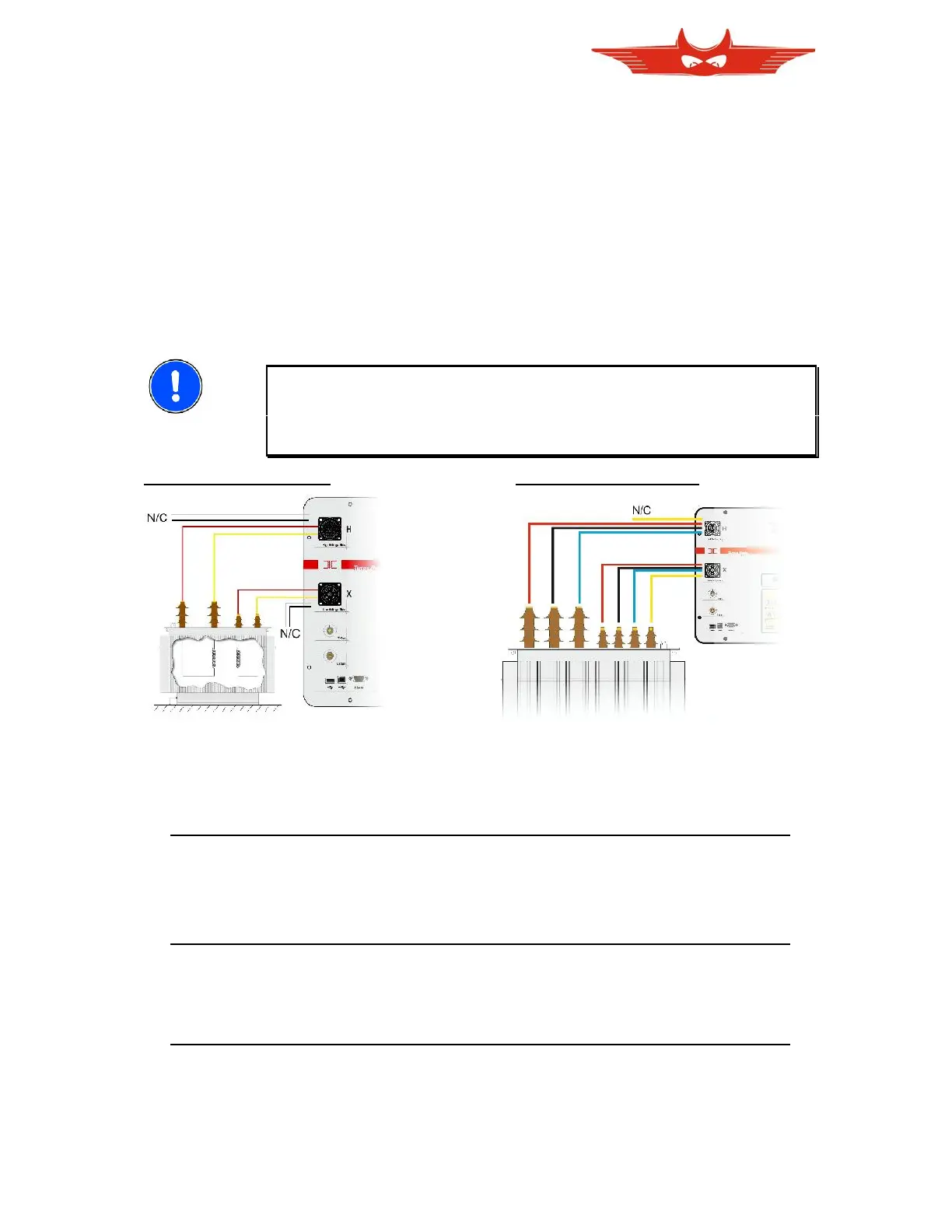
Single Phase Transformer Three Phase Transformer
The colored leads are marked to indicate which transformer terminal it must be connected to
for correct operation.
For a Single (1) phase transformer, use leads:
WIRE COLOR ANSI IEC ANSI IEC
- RED indicates H1 U phase (Red clip) or X1 u phase (Black clip)
- YELLOW indicates H0 N neutral(Red clip) or X0 n neutral (Black clip)
For a Single (1) phase auto-transformer, use leads:
WIRE COLOR ANSI IEC ANSI IEC
- RED indicates H1 U phase (Red clip) or X1 u phase (Black clip)
- Black indicates H2 V neutral(Red clip) or X2 v neutral (Black clip)
For a Three (3) phase transformer, use leads:
WIRE COLOR ANSI IEC ANSI IEC
- RED indicates H1 U phase (Red clip) or X1 u phase (Black clip)
- BLACK indicates H2 V phase (Red clip) or X2 v phase (Black clip)
- WHITE indicates H3 W phase (Red clip) or X3 w phase (Black clip)
- YELLOW indicates H0 N neutral(Red clip) or X0 n neutral (Black clip)