Do you have a question about the Raytech TR–Mark III 250V and is the answer not in the manual?
Only qualified persons should operate the equipment and keep clear of high voltage apparatus during tests.
Ensure the instrument is grounded and follow pre-power checks to minimize shock hazards.
Avoid live circuits, do not remove covers, and disconnect power before touching components.
Lists the standard items provided with the TR-Mark III 250V instrument upon unpacking.
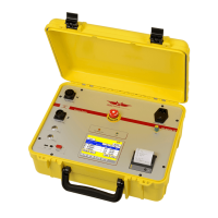
Describes the waterproof design of the field case and its automatic pressure compensation feature.
Details the development and technological advancements of the TR-Mark III from previous generations.
Covers ease of use, accuracy, measurement technique, safety protection, and simple maintenance.
Lists various features including LCD, automatic measurements, ruggedness, connectivity, and accuracy specifications.
Explains the instrument's self-check process performed upon powering on for system integrity.
Details the methodology and purpose of performing transformer turns ratio testing with the instrument.
Lists common applications such as identifying shorted turns, tap errors, and mislabelled terminals.
Discusses limitations like phase relationships and winding types, suggesting the T-Rex unit as an alternative.
Provides a step-by-step guide for initial instrument operation and performing a measurement.
Details lead connections for single and three-phase transformers using color coding and standard terminals.
Compares wire colors for ANSI, IEC, and Australian standards for high and low winding sides.
Identifies and labels all components on the front panel of the instrument, including ports and controls.
Explains the function of key controls like power switch, emergency stop, and input/output terminals.
Describes T-Rex, External, Interface ports, and the function of Safety Indicator lights (Green/Red).
Details the touch screen display interface and the built-in thermal printer for results.
Illustrates and labels the front panel components of the rack-mounted version of the instrument.
Illustrates and labels the rear panel connections and ports of the rack-mounted unit.
Explains the benefits of storing measurement data to save time and reduce manual errors.
Describes how transformer profiles and measurements are created, stored, and linked together.
Presents a diagram illustrating the instrument's menu structure and navigation flow.
Explains how to perform a measurement when no specific transformer data has been entered.
Describes how to select and measure individual phases instead of performing a full three-phase test.
Explains how to change the test voltage setting directly from the main test screen.
Details how to stop an ongoing measurement or run it continuously on a selected phase.
Explains how to switch between displaying turns ratio and voltage ratio calculations.
Details the procedures for printing or saving the measurement results obtained from the test.
Shows how results display pass/fail status and how to enter transformer names for identification.
Describes the options for displaying turns ratio or voltage ratio and their calculation basis.
Explains how the instrument displays and controls tap steps, allowing step-by-step measurements.
Demonstrates selecting tap changer positions based on nominal voltage values for transformer testing.
Explains how to manage transformers with tap changers on both primary and secondary winding systems.
Describes how to select and measure transformers that feature a tertiary winding system.
Explains managing tertiary tap changers and primary tap changes when switching winding systems.
Presents options for creating a new transformer, loading from archive, copying, or making a new measurement.
Guides the user through creating a new transformer profile without taps, selecting test voltage and type.
Explains how to define tap steps and associate voltages for transformer taps on primary and secondary windings.
Details activating the tertiary option and defining taps for the third winding system.
Explains how to load, clone, or manage transformer data stored locally or on a memory stick.
Describes copying an existing transformer's settings to create a new, similar profile for identical objects.
Explains how to save multiple measurements using the 'New Measurement' option to avoid overwriting.
Details creating and using templates for testing multiple similar transformers efficiently.
Describes inputting primary, secondary, and tertiary voltage data for ratio calculations and tap settings.
Explains entering transformer name, serial number, manufacturer, type, and other identifying details.
Covers setting maximum ratio deviation and selecting international standards (IEC, ANSI, Australian).
Describes how to view a sorted list of results and graphics, noting read-only or read/write access.
Explains how to use the wizard to automatically enter tap changer data, including nominal voltages.
Describes manually entering designator and voltage for each tap step, useful for non-linear taps.
Explains managing data in the archive, including loading, deleting, importing, and exporting via USB.
Covers license, about, clock, cursor, update, language, and service menu configurations.
Details settings for operator logging and selecting international standards for transformer testing.
Explains configuration options for printers and selecting display color schemes for readability.
Manages license keys, displays instrument info (firmware, serial), and sets the system date and time.
Controls cursor, manages firmware updates, selects languages, and accesses service menus.
Discusses operator logging for measurements and selecting international standards for testing.
Covers settings for external/internal printers and choosing display color schemes for optimal contrast.
Details ratio, current, and phase angle measurement parameters, ranges, and their respective accuracies.
Lists model, dimensions, weight, input power, test voltage options, display, and interface details.
Describes optional accessories like the T-Rex voltage option and rackmount version for enhanced functionality.
Details the connections, parameters, and pin assignments for RS232, T-Rex extension, and USB ports.
Explains the interface for external tap switches, including trigger functionality and warning device connections.
Describes the Raytech Toolbox software for data exchange and updating the instrument's firmware.
Details the hardware protocol (RS232) and software protocol requirements for remote control operations.
Explains how to use remote commands, syntax, and how to obtain the complete command set.
Provides contact addresses for Raytech GmbH in Switzerland and Raytech USA, Inc.
Explains the nature of current transformers and how the instrument tests them by applying voltage.
Details lead connections and initial steps for measuring current transformers for highest accuracy.
Addresses 'Overcurrent' messages for low impedance CTs by recommending lower test voltages.
Explains CT ratio definition in info fields and testing CTs with multiple tapped secondaries.
Shows an example of a test report generated by the instrument's built-in thermal printer.
Displays an example test report formatted for printing via an external USB printer.
Explains how to update the TR-Mark III 250V firmware via a USB memory stick for new releases.
Lists and explains common error messages like 'No Test Leads', 'Emergency Pressed', and 'Overcurrent'.
Provides steps to resolve issues where the system display or touch panel is not functioning correctly.
Offers solutions for problems preventing measurement startup or USB memory stick recognition.
Outlines the 5-year warranty period and conditions for the TR-Mark III 250V, including return requirements.
Details warranty exclusions, limitations, and the scope of liability concerning product misuse or unauthorized modifications.
| Brand | Raytech |
|---|---|
| Model | TR–Mark III 250V |
| Category | Test Equipment |
| Language | English |