Instruction Manual TR-Mark III 250V Version 1.10 Preliminary Page 50 of 57
A.A Current Transformer Testing
A.A.A Introduction
Current transformers are, in effect, opposite wound voltage transformers. This basically
means that the largest number of windings are on the “X” (low current) side of the current
transformer.
The TR-Mark III 250V applies a voltage (from 1 to 250 VAC) from the “H” leads and
measures back through the “X” leads. The “X” leads always must have a lower voltage than
the “H” leads or an error will be displayed. Therefore, when testing Current transformers the
“H” test leads are connected to the “X” terminal of the Current Transformer.
NOTE
For CT testing, “H” leads are connected to the “X” terminal of the
Current Transformer.
A.A.B Usual Measurement
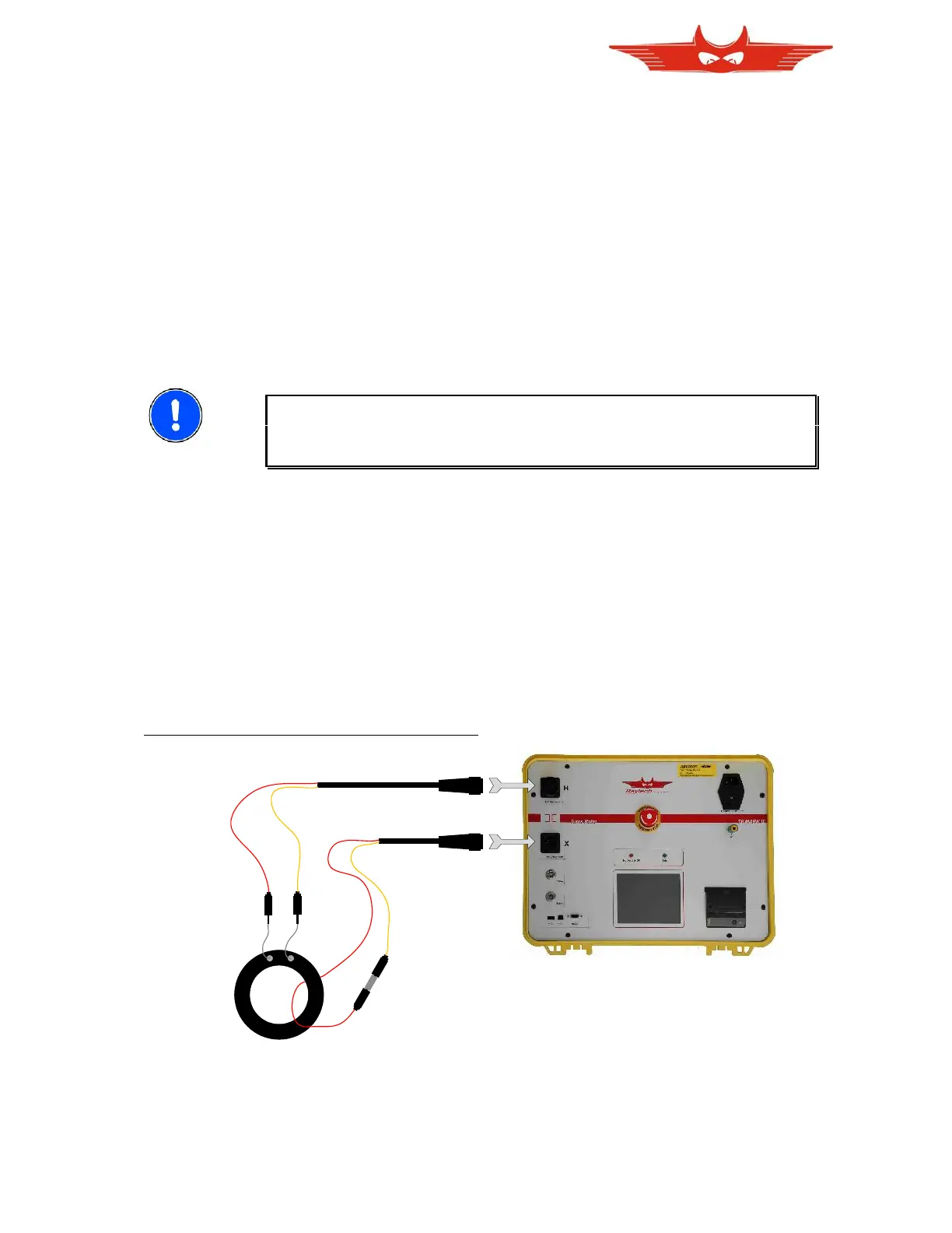
Connect the test leads as shown. For the highest accuracy, create a new transformer and
select CT. Use 10V to start. Use 40V test voltage for very big ratios only.
CT is selected for Current Transformers exclusively. This test set has a special Voltage /
Current function built-in for Current Transformers. If an error is still present after using 10V,
use test voltage 1V.
1. Connect a Current Transformer as following: