Instruction Manual TR-Mark III 250V Version 1.10 Preliminary Page 12 of 57
5 Operation Elements
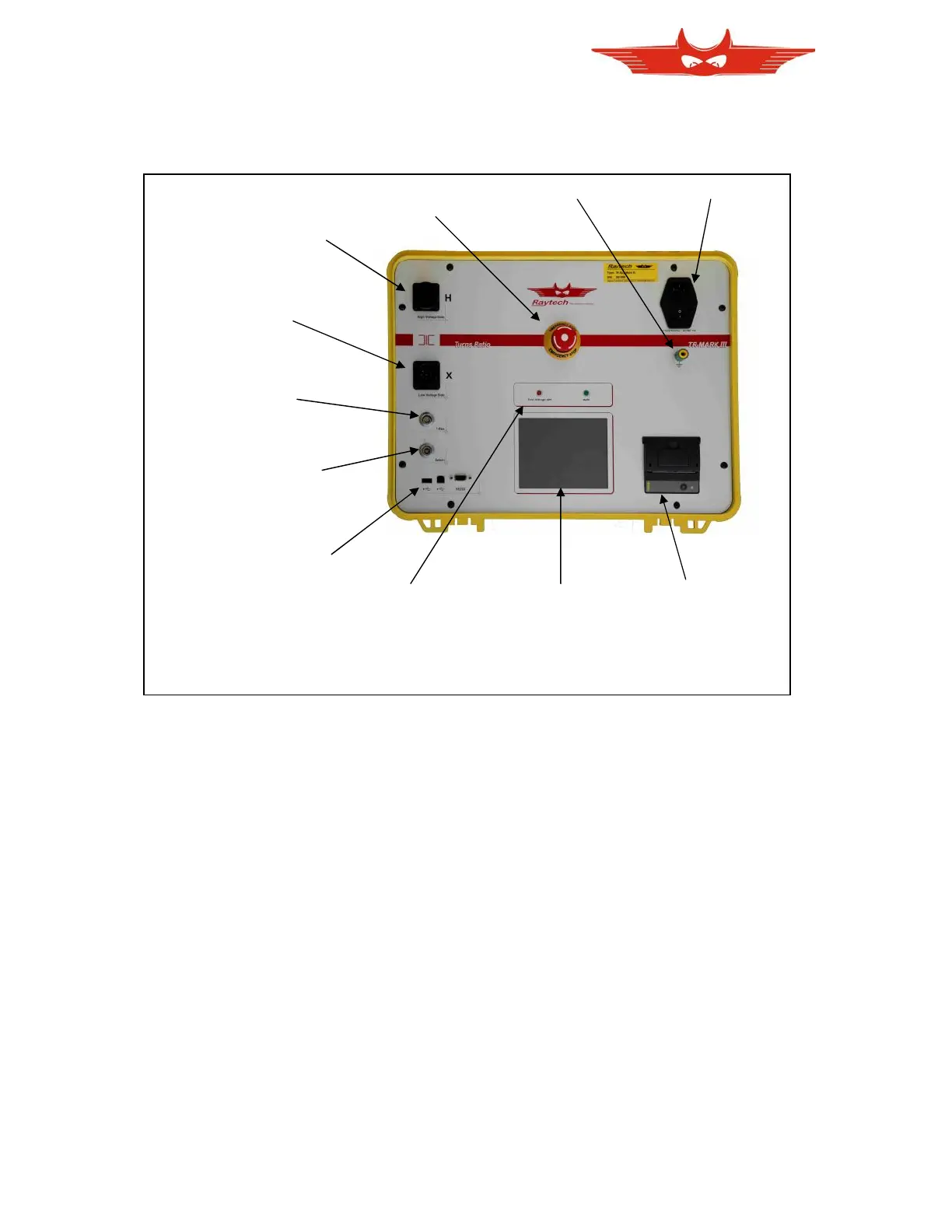
5.1 Front Panel Overview:
5.2 Control Elements and Connections
5.2.1 Fuse, Mains Input and Switch
A 2A fuse (slow blow) protects the device. Use only the correct fuse type to replace it.
5.2.2 Ground Terminal
Use this terminal to connect an additional ground line even if your mains Power cable
(Mains) provides an Earth ground line. Also, use it even if you are not sure that the local
installation Earth ground is a low resistive ground.
5.2.3 Emergency Off
Press to Stop. The system will halt and cease Voltage to the test leads immediately. Turn
clockwise to release. The device will remain in a safe state.
5.2.4 High Voltage Side
The connector for the High side lead (H) to test object.
5.2.5 Low Voltage Side
The connector for the Low side lead (X) to test object.