SensorLocation
MarathonSeriesFA/FR 13
4SensorLocation
Sensorlocationandconfigurationdependsontheapplication.Beforedecidingonalocation,youneed
to be aware of the ambient temperature of the location, the atmospheric quality of the location
(especially for 1‐color temperature measurements), and the possible electromagnetic interference in
thatlocation(a considerationonlyforthe electronics
enclosure).Ifyouplantouseairpurging,you
needtohaveanairconnectionavailable.Also,wiringandconduitrunsmustbeconsidered,including
computerwiringandconnections,ifused.Thefollowingsubsectionscovertopicstoconsiderbefore
youinstallthesensor.
4.1AmbientTemperature
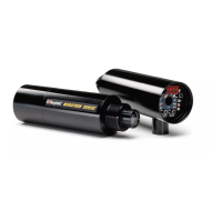
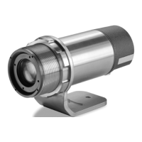
Theopticalheadisdesignedtooperateinambienttemperaturesupto200°C(390°F).Theelectronics
enclosureisdesignedtooperate inambienttemperaturesbetween0°C(32°F)and60°C(140°F).The
internalambienttemperaturecanvaryfrom10°C(50°F)to68°C(154°F).Internaltemperaturesoutside
thisrangewillcauseafailsafe
error.
4.2AtmosphericQuality
Smoke, fumes, dust, and other contaminants in the air, as well as a dirty lens are generally not a
problem when using the 2‐color mode (as long as the attenuation is equal in both spectral bands).
However,ifthelensgetstoodirty,itcannotdetectenoughinfraredenergyto
measureaccurately,and
theinstrumentwillindicateafailure.Itisgoodpracticetoalwayskeepthelensclean.TheAirPurge
Collarhelpskeepcontaminantsfrombuildinguponthelens.Ifyouuseairpurging,makesureanair
supplywiththecorrectairpressureisinstalledbefore
proceedingwiththesensorinstallation.
4.3ElectricalInterference
Tominimizeelectricalorelectromagneticinterferenceor“noise”beawareofthefollowing:
• Mount the electronics enclosure as far away as possible from potential sources of electrical
interferencesuchasmotorizedequipmentproducinglargesteploadchanges.
• Useshieldedwireforallinputandoutputconnections.
• Makesurethe
shieldwirefromtheelectronicstoterminalblockcableisearthgrounded.
• Foradditionalprotection,useconduitfortheexternalconnections.Solidconduitisbetterthan
flexibleconduitinhighnoiseenvironments.
• DonotrunACpowerforotherequipmentinthesameconduit.
When installing the optical head, check for any high‐intensity discharge lamps or
heaters that may be in the field of view (either background or reflected on a shiny
target)!Reflectedheatsourcescancauseasensortogiveerroneousreadings.
4.4DistancetoObject
The requested spot size determines the maximum distance to the measurment object and the
necessaryfocusoftheoptic.TheStandardFocusissetatinfinity.TheCloseFocusopticalheadsare
focusedat100mm(4in)or300mm(12in),seesection
3.5OpticalSpecifications,p.9.