COMMUNICATION PORTS
SYNC (VIDEO SYNC IN) WITH SYNC TRIGGER BUTTON CIRCUIT
The DSMC2 Base Expander features a SYNC connector with a SYNC Trigger Button Circuit.
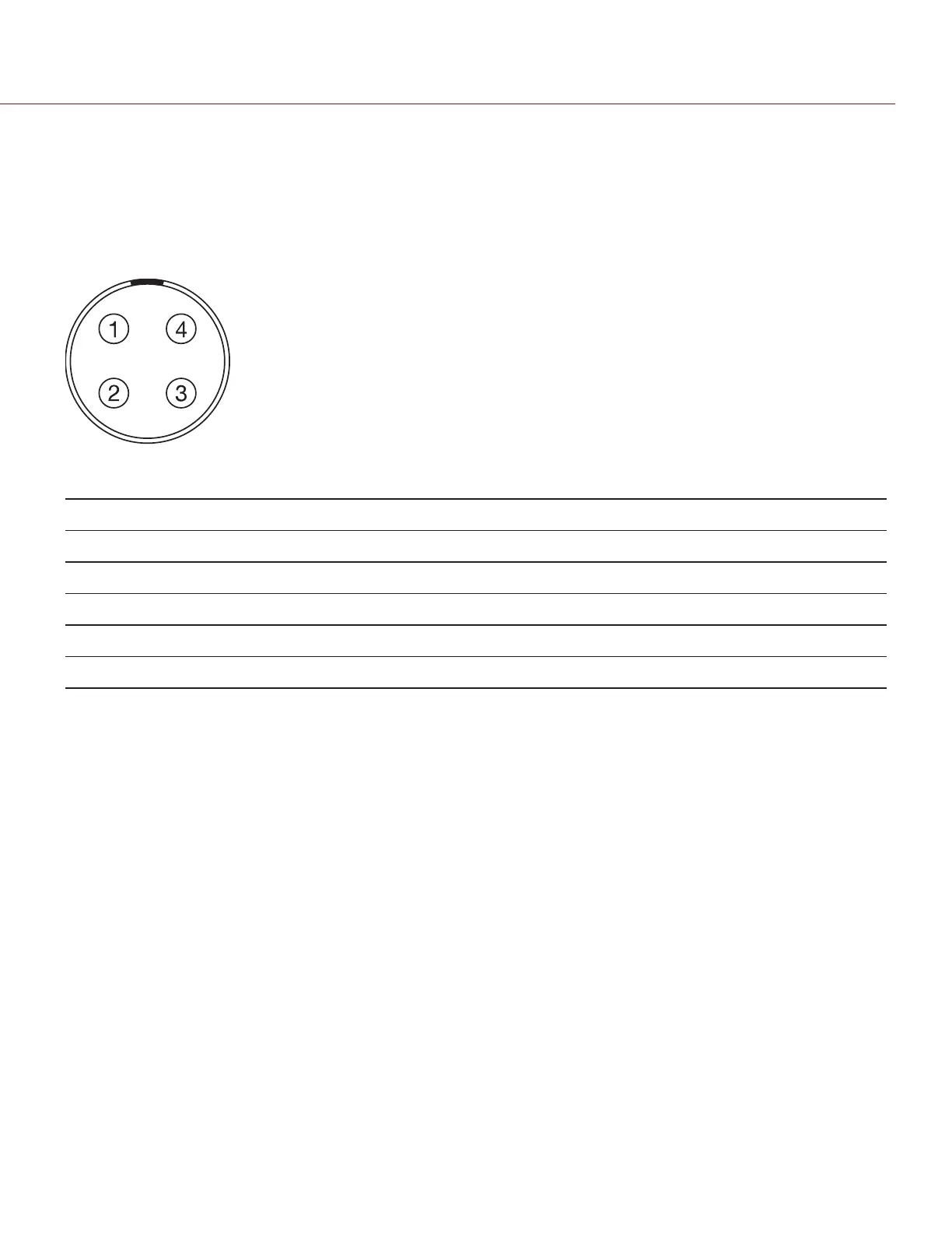
The 4-pin 00B LEMO SYNC connector accepts timecode, genlock, and General Purpose Input (GPI) signals.
Figure: Front Face of the SYNC (Video Sync) Connector (Looking at the Camera)
4-PIN 00B LEMO SYNC CONNECTOR
PIN SIGNAL DESCRIPTION DIRECTION
1 GROUND Common ground N/A
2 SS/GPI Shutter sync/general purpose input trigger In
3 TIMECODE SMPTE unbalanced timecode input In
4 GENLOCK Tri-level sync input In
NOTE: Mating connector is FGG.00.304.CLAD.
C OPYRI GHT © 2017 R ED.C O M , I NC 955- 01 38 _V6.3, REV-D | 223
WEAPON/EPIC-W OPERATION GUIDE