SERIAL (RS232 CONTROL)
The DSMC2 REDVOLT Expander features a SERIAL connector. The 7-pin 0B LEMO SERIAL connector supports
RS232 RX, RS232 TX, and a General Purpose Input (GPI) trigger (active-low switch closure). The connector also offers
auxiliary power out, with a maximum sustained current draw of 1.5A.
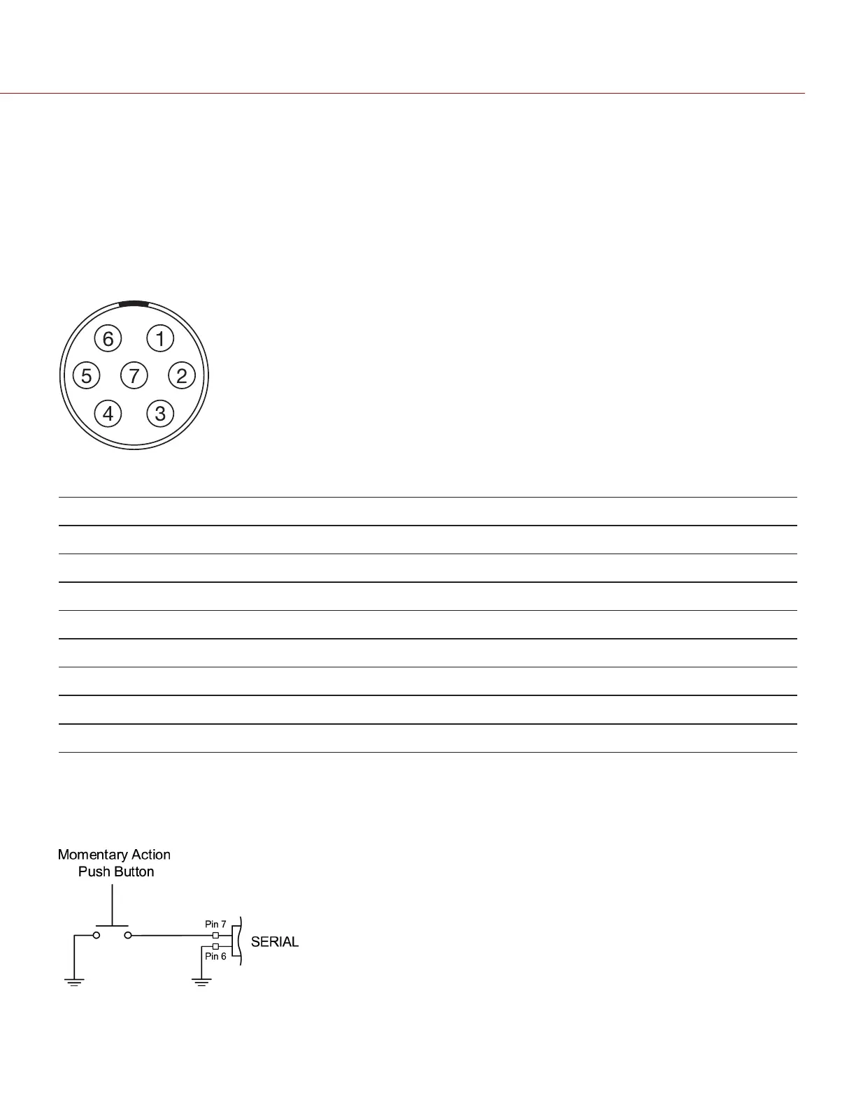
To operate the GPI contact closure style trigger, short Pin 7 (GPI) to Pin 6 (ground).
The SERIAL connector was designed to support 6-pin 0B cables used with the RED Tactical Hand Controller (T.H.C.).
Although the connectors on those cables do not have pin 7 (GPI), the other 6 pins do match pins 1 to 6 on the SERIAL
connector.
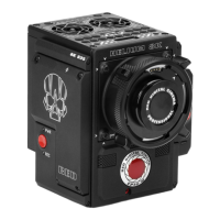
Figure: Front Face of the SERIAL (RS232) Connector (Looking at the Camera)
SERIAL CONNECTOR
PIN SIGNAL DESCRIPTION DIRECTION
1 GND Camera ground N/A
2 RS232 RX RS232 RX In
3 RS232 TX RS232 TX Out
4 AUX OUT +11.5 to +17 VDC unregulated battery pass-through power Out
5 N/A No connection (NC) N/A
6 GND Camera ground N/A
7 GPI General Purpose In (GPI) trigger (active-low switch closure) In
NOTE: Mating connectors are FHG.0B.307.CLAD (right-angle) or FGG.0B.307.CLAD (straight).
CONTACT CLOSURE STYLE TRIGGER BUTTON CIRCUIT (SERIAL)
The diagram below shows the contact closure style trigger button circuit on the SERIAL connector.
Figure: Contact Closure Style Trigger Button Circuit Diagram (SYNC)
C OPYRI GHT © 2017 R ED.C O M , I NC 955- 01 38 _V6.3, REV-D | 228
WEAPON/EPIC-W OPERATION GUIDE