Reflexomat with Touch controller — 06.07.2016 - Rev. B English —
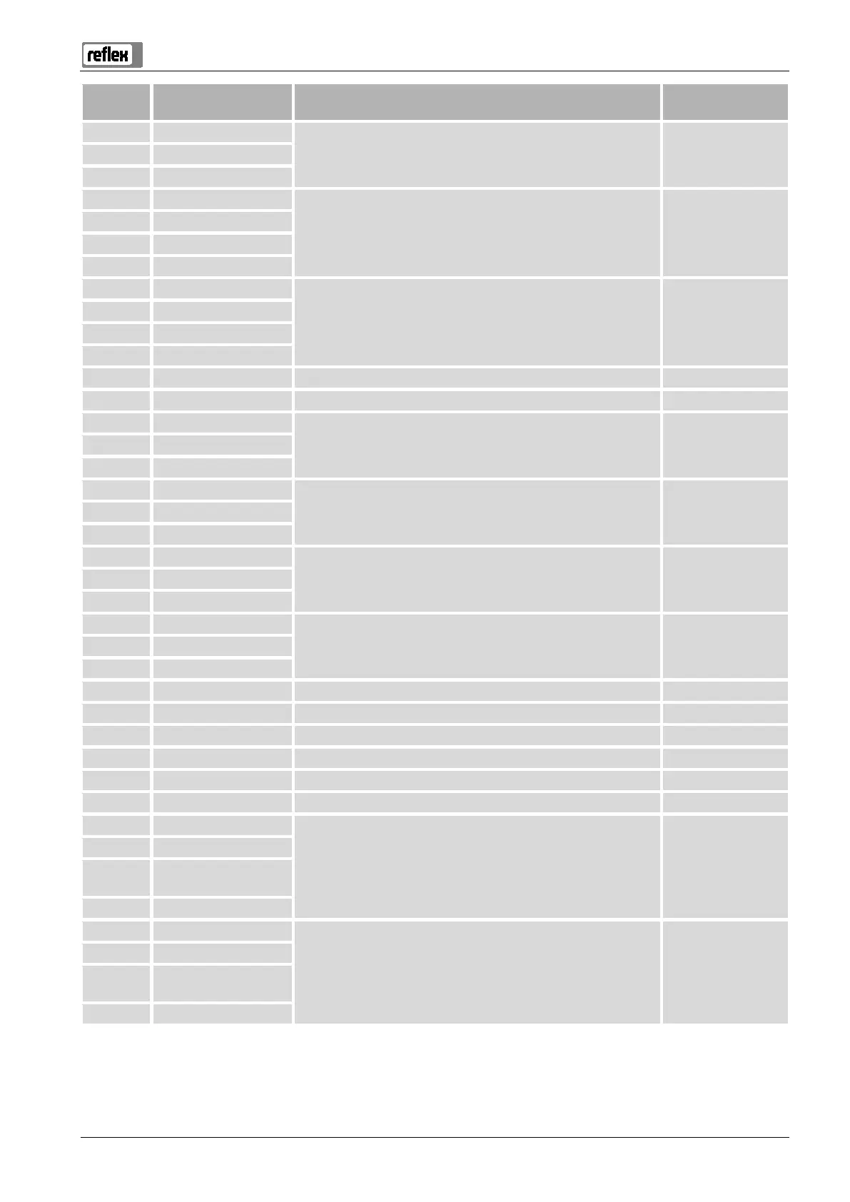
Terminal
number
Signal Function Wiring
23 NC
Group message (floating) User, optional 24 COM
25 N.O.
35 +18 V (blue)
Analogue input, LIS level measuring
at the primary tank
User supplied
36 GND
37 AE (brown)
38 PE (shield)
39 +18 V (blue)
PIS pressure sensor analogue input at the primary tank User, optional
40 GND
41 AE (brown)
42 PE (shield)
43 +24 V Digital inputs User, optional
44 E1 E1: Contact water meter Factory-provided
1 PE
Voltage supply Not assigned 2 N
3 L
10 Y3
PV 2 solenoid valve Factory-provided 11 N
12 PE
15 M1
Compressor 1 with 230 V systems,
with 400 V systems via 6K1 motor protection
Factory-provided 16 N
17 PE
18 M2
Compressor 2 with 230 V systems,
with 400 V systems via 6K1 motor protection
Factory-provided 19 N
20 PE
21 FB1 Compressor 1 voltage monitoring Factory-provided
22a FB2a Compressor 2 voltage monitoring Factory-provided
22b FB2b External make-up request together with 22a ---
27 M1 Flat plug for supply, compressor 1 Factory-provided
31 M2 Flat plug for supply, compressor 2 Factory-provided
45 E2 E2: Insufficient water switch Factory-provided
51 GND
Solenoid valve 2 ---
52 +24 V (supply)
53 0 – 10 V (correcting
variable)
54 0 – 10 V (feedback)
55 GND
Solenoid valve 1 ---
56 +24 V (supply)
57 0 – 10 V (correcting
variable)
58 0 – 10 V (feedback)