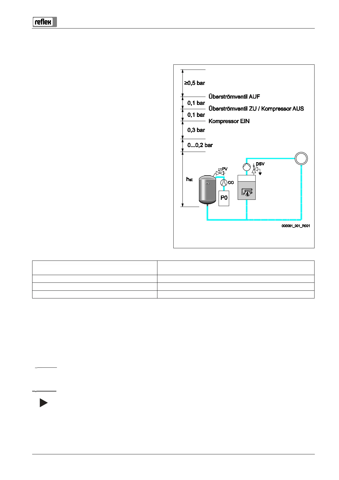
Reflexomat with Touch controller — 06.07.2016 - Rev. B English —
Determining the P
0
minimum operating pressure for the controller
The "P
0
" minimum operating pressure is determined by the location of the pressure maintaining device. The controller calculates the
switching points for the "PV" solenoid valve and the "CO" compressor from the "P
0
" minimum operating pressure.
Actuating pressure for the "P
sv
" safety valve
Solenoid valve "OPEN" = final pressure "P
e
"
Solenoid valve "CLOSED" / Compressor "OFF"
Compressor "ON" = initial pressure "P
a
"
Minimum operating pressure "P
0
"
Static pressure "P
st
"
The "P
0
" minimum operating pressure is calculated as follows:
P
0
= P
st
+ P
D
+ 0.2 bar* Enter the calculated value in the start routine of the controller, see
chapter 7.3 "Modifying the controller's start routine" on page 36 .
P
st
= h
st
/10 h
st
in metres
P
D
= 0.0 bar for safety temperatures ≤ 100 °C
P
D
= 0.5 bar for safety temperatures = 110 °C
*Addition of 0.2 bar recommended, no addition in extreme cases
Calculation example for "P
0
" minimum operating pressure:
Heating system: Static height 18 m, run-on temperature 70 °C, safety temperature 100 °C.
Calculation example:
P
0
= P
st
+ P
D
+ 0.2 bar*
P
st
= h
st
/10
P
st
=18 m/10
P
st
= 1.8 bar
P
D
= 0.0 bar at a safety temperature of 100 °C
P
0
= 1.8 bar + 0 bar + 0.2 bar
P
0
= 2.0 bar
Notice!
Avoid dropping below the "P
0
"minimum operating pressure. Vacuum, vaporisation and cavitation are thus excluded.