EasyManua.ls Logo

Resol EM User Manual

Resol EM
80 pages
Go to English
To Next Page IconTo Next Page
To Previous Page IconTo Previous Page
Page #42 background imageLoading...
Page #42 background image
42
fr
!
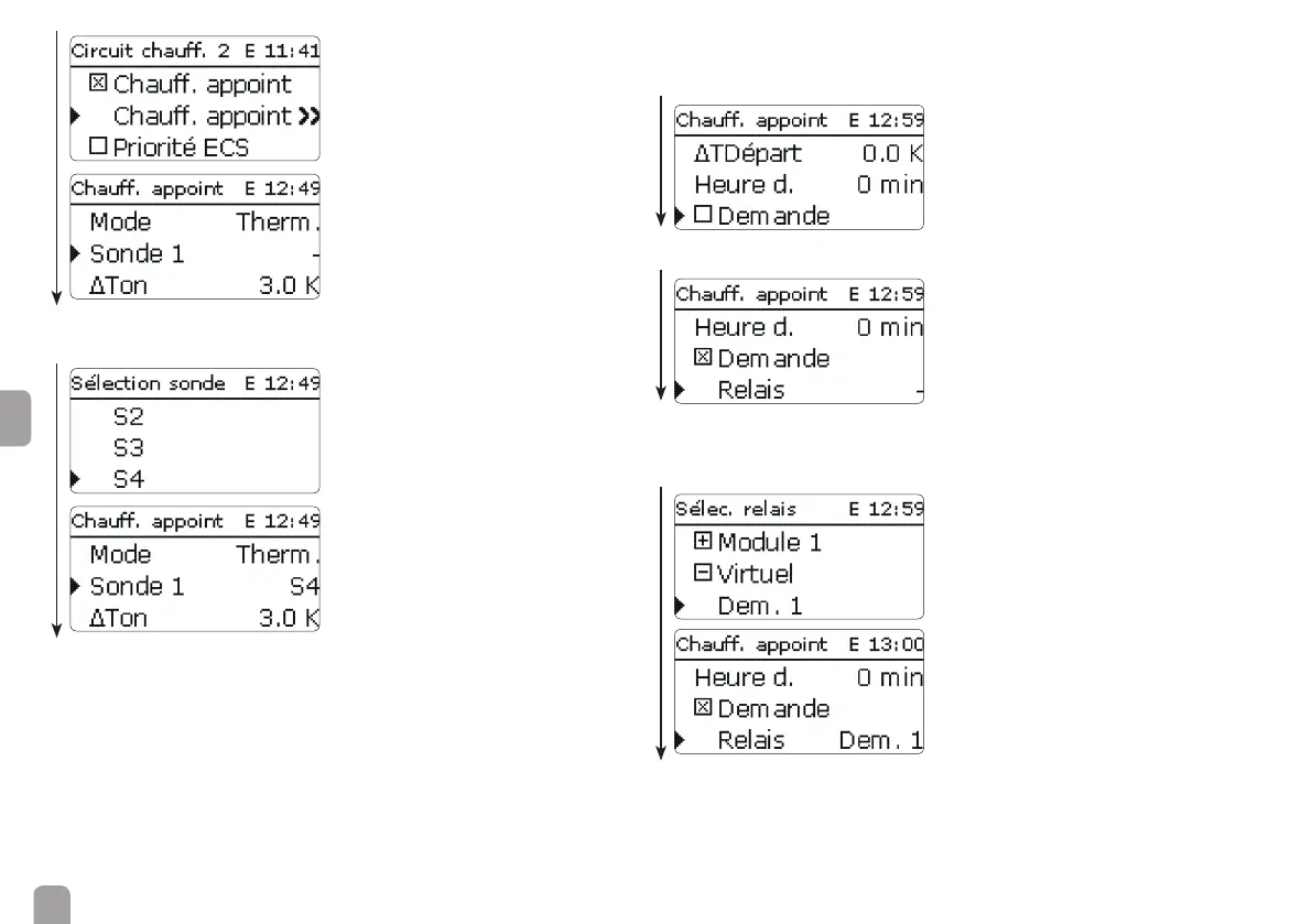
Lorsque le chauffage d‘appoint est activé, la sonde commune S4 du régulateur doit
être attribuée au module d‘extension.
Î Activez la demande.
Il est possible d‘activer une demande ou la pompe de charge de la chaudière pour
le chauffage d‘appoint.
Les schémas du DeltaTherm
®
HC sont déjà pré-con gurés. Les demandes et
la pompe de charge de la chaudière sont attribuées au chauffage d’appoint par des
relais communs.
Î Sélectionnez le relais pour la demande.
!
Lorsque la demande est activée, le relais commun (R5) du régulateur doit être
attribué à la demande.
(Menu principal / Chauffage / Relais communs / Dem. 1 / Relais / Sortie R5)
La mise en service du module d‘extension pour la commande d‘un deuxième circuit
de chauffage est maintenant terminée.

Table of Contents

Question and Answer IconNeed help?

Do you have a question about the Resol EM and is the answer not in the manual?

Resol EM Specifications

General IconGeneral
BrandResol
ModelEM
CategoryControl Unit
LanguageEnglish

Summary

Safety and General Information

Safety Advice

Instructions to avoid danger and damage to people and property.

Product Handling and Compliance

Proper usage, CE conformity, and environmentally sound disposal.

Symbols and Warnings

Explains warning, attention, note, and instruction symbols.

1 Overview

Key Features

Highlights include quick access, optional functions, VBus connection, and configuration.

Technical Data

Detailed specifications for inputs, outputs, power supply, and operating conditions.

2 Installation

2.1 Mounting

Step-by-step guide for physically mounting the device on a wall.

2.2 Electrical Connection

Instructions for connecting sensors, relays, and mains power supply.

2.3 Data Communication / Bus

Details on establishing communication via the RESOL VBus® interface.

3 Initial Commissioning

Connection and Setup

Connecting the EM module to the controller and system components.

Configuration Steps

Registering module, selecting relays, and setting up heating circuits.

4 Operation

4.1 Buttons

Explanation of the device's operation using the three buttons.

4.2 Selecting Channels and Adjusting Values

How to navigate menus and modify settings using buttons.

4.3 Slide Switch

Functionality of the manual/automatic mode selection slide switch.

4.4 Flashing Codes and Warning Symbols

Interpreting LED status indicators and on-screen warning symbols.

5 Menu System

5.1 Channel Overview

List of all available channels, their descriptions, and page references.

5.2 Display Channels

Details on channels for displaying error codes, version, and sensor values.

5.3 Adjustment Channels

Information on channels for manual mode, slide switch settings, and sensor types.

6 Troubleshooting

Troubleshooting Steps

Guidance on identifying and resolving common malfunctions.

Fuse Replacement

Procedure for checking and replacing the device's fuse.

7 Accessories

7.1 Sensors

Overview of available temperature sensors and their specifications.

Overvoltage Protection Device

Recommendation for installing RESOL SP10 to protect sensors.

Related product manuals