Table of Contents
Page
1 Mechanical Installation.......................................................................... 1
1.1 Visual Check.......................................................................................... 1
1.2 Ambient Conditions............................................................................... 1
1.3 Figures and Dimensions......................................................................... 2
1.3.1 Standard Models.................................................................................... 2
1.3.2 Wall-Through Models.............................................................................. 7
1.4 Installation........................................................................................... 10
1.4.1 Installation Conditions......................................................................... 10
1.4.2 Installation Instructions for Wall-Through Models............................... 11
Whole Facility Installation.................................................................... 11
Cooling System.................................................................................... 11
1.4.3 DIN Rail Mounting................................................................................ 13
2 Electric Installation.............................................................................. 14
2.1 Overview of Electric Connections........................................................ 14
2.2 Cable Specifications............................................................................ 15
2.2.1 Power Connection............................................................................... 15
Cable specification for international without USA / Canada............... 15
Cable specification for USA / Canada.................................................. 17
2.2.2 Control Signal Connection................................................................... 19
2.3 Terminals............................................................................................. 20
2.3.1 Power Terminals.................................................................................. 20
2.3.2 Control Terminals................................................................................ 22
Control terminals figure....................................................................... 22
Control terminals description.............................................................. 23
Digital input NPN / PNP wiring............................................................ 25
Digital output DO1a, DO1b load pull-up / pull-down wiring................ 26
Analog input terminals (AI1, AI2, EAI, +10 V, +5 V, Earth and GND).... 27
Relay output terminals......................................................................... 28
3 Start-up................................................................................................ 29
3.1 LED Panel and Dust Cover................................................................... 29
3.1.1 LED Panel............................................................................................ 29
3.1.2 Dust Cover........................................................................................... 30
3.1.3 LED Indicator....................................................................................... 31
3.1.4 Operating Descriptions........................................................................ 32
3.2 LCD Panel............................................................................................ 33
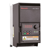
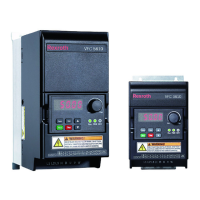
Rexroth Frequency Converter VFC
3610 / VFC 5610
I
Table of Contents
R912005518_Edition 16 Bosch Rexroth AG