1.4 Installation
1.4.1 Installation Conditions
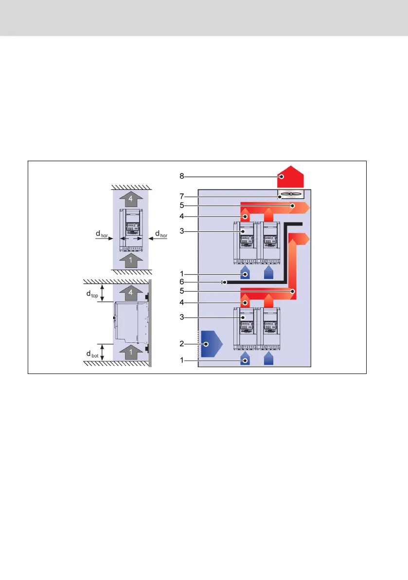
The frequency converter must be installed vertically.
If one frequency converter is arranged above another, make sure the upper limit
of air temperature into the inlet is not exceeded (see "Technical Data" in the
Operating Instructions). An air guide is recommended between the frequency
converters to prevent the rising hot air being drawn into the upper frequency
converter if the upper limit of air temperature is exceeded.
Fig. 1-12: Mounting distance and arrangement
d
hor
(Distance horizontal):
d
hor
= 0 mm (0K40...22K0); d
hor
= 10 mm (30K0...185K)
d
top
(Minimum top distance):
d
top
= 125 mm (0K40...90K0); d
top
= 400 mm (110K...220K)
d
bot
(Minimum bottom distance):
d
bot
= 125 mm (0K40...90K0); d
bot
= 400 mm (110K...220K)
1: Air inlet at frequency converter; 2: Air inlet at control cabinet
3: Frequency converter; 4: Air outlet at frequency converter
5: Heated air conveying direction; 6: Air guide in control cabinet
7: Fan in control cabinet; 8: Discharge of heated air
10/91
Mechanical Installation
Rexroth Frequency Converter VFC
3610 / VFC 5610
Bosch Rexroth AG R912005518_Edition 16