ASMxxxx Series User’s Manual
Asia Pacific | EMEA | Americas 13
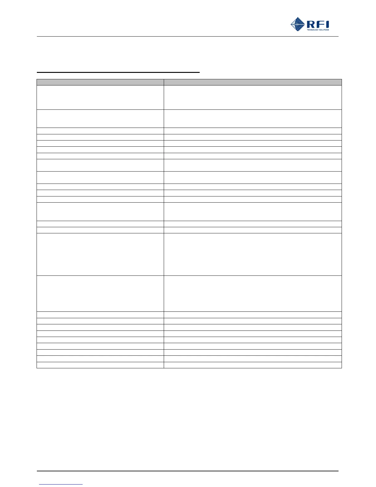
3. ASM - Electrical and Mechanical Specifications
Frequency range
(Tx power and Rx level monitoring)
ASM1317 132-174MHz
ASM3852 380-520MHz
ASM7487 746-870MHz
ASM8796 870-960MHz
Maximum number of monitored channels
Tx = 80
Rx = 80
System Isolation Tests = 20
Maximum number of Tx networks (Tx ant’s)
4 (can be externally expanded)
Maximum number of Rx networks (Rx ant’s)
1 (can be externally expanded)
Frequency channel step size
Channel measurement bandwidths
Max spurious or IM products level
Measurable Rx input power level
-50dBm to -110dBm
(the RSM module can enhance ASM readings to better than -125dBm)
Measurable Tx input power level
-30dBm to +20dBm (minimum range)
(i.e. +10dBm to +60dBm into 40dB coupler)
Complies with CISPR22 Part B & FCC Part 15 (15.207)
Complies with CISPR22 Part B & FCC Part 15 (15.209)
RF Termination connectors
Communication interface ports
“K1” hardware variant
“K2” hardware variant
1 x USB Type B, 1 x TCPIP RJ45 Ethernet port on rear
2 x TCP/IP RJ45 Ethernet ports on rear
Internal alarm relay contacts output connector
Visual alarm notification
Summary Fault / Tx FWD min. power
Tx FWD max. power / Tx Combiner I.L. max.
VSWR max. / Rx RSSI min. level / RSSI max. level
Tx-to-Rx Antenna Isolation min. & max.
Rx System Gain Loss min. & max.
Tx Carrier Rejection min. & max.
(optional CAM/SAM module alarms)
Summary Alarms – ASM Relay Outputs
Detailed or Group Alarms – ASM or CAM/SAM Module Relay Outputs
SMTP Email (up to 4 Addresses)
SNMPv2c (Northbound Traps or Southbound GET)
or via Genesis Software GenWatch™ ASM Applet
or via C² Systems SitePortal® monitoring software
Dry Relay N.O. / Common / N.C.
Alarm Relay Contact Ratings
9-36VDC, 36-60VDC, or 90-264VAC
1 x Polarized 2-pin Phoenix-style connector on rear
W 19 x H 3.5 x D 1.6in / W 483 x H 89 x D 40mm (incl. connectors)
Operational temperature range
-22°F to 140°F / -30°C to +60°C