9
20152192
Technical description of the burner
4.4 Electrical data
Tab. D
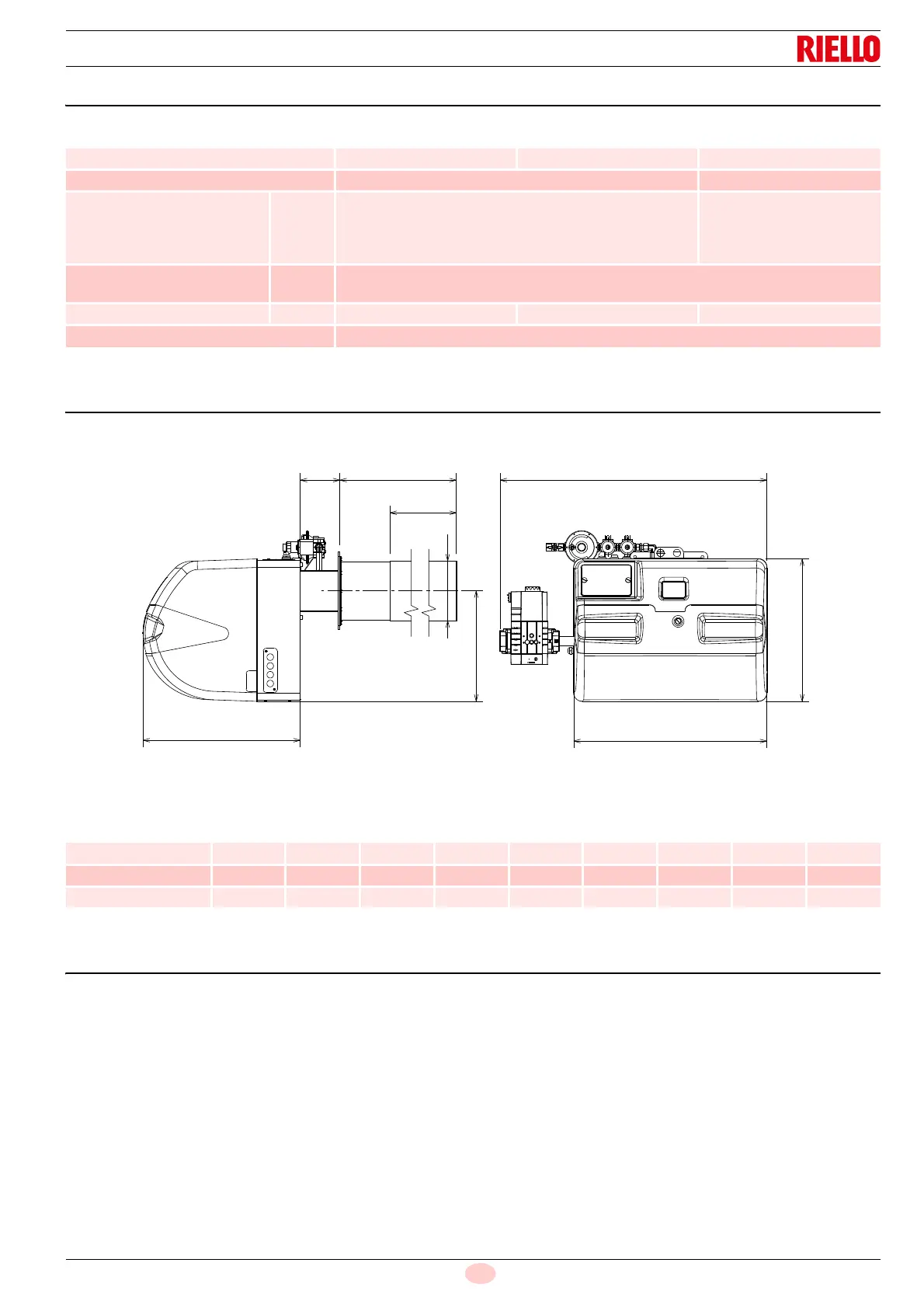
4.5 Maximum dimensions
The maximum dimensions of the burner are given in Fig. 1.
Tab. E
4.6 Burner equipment
Pilot gas train . . . . . . . . . . . . . . . . . . . . . . . . . . . . . . . . . . . No. 1
Flange for gas train . . . . . . . . . . . . . . . . . . . . . . . . . . . . . . No. 1
Screws to fix the flange . . . . . . . . . . . . . . . . . . . . . . . . . . . No. 4
Insulating gasket . . . . . . . . . . . . . . . . . . . . . . . . . . . . . . . . No. 1
Gas valve with flange and gas pipe . . . . . . . . . . . . . . . . . . No. 1
Instructions . . . . . . . . . . . . . . . . . . . . . . . . . . . . . . . . . . . . . No. 1
Spare parts list . . . . . . . . . . . . . . . . . . . . . . . . . . . . . . . . . . No. 1
Hardware for burner assembly:
M10 x 50 Stainless steel nuts (with or without tip) . . . . . . . No. 4
Zinc plated washers M10 x 16 . . . . . . . . . . . . . . . . . . . . . . No. 4
Toothed washers M10 . . . . . . . . . . . . . . . . . . . . . . . . . . . . No. 4
M10 Zinc-plated nuts . . . . . . . . . . . . . . . . . . . . . . . . . . . . . No. 4
Compensation pipe. . . . . . . . . . . . . . . . . . . . . . . . . . . . . . . No. 1
Model RX 700 S/PV RX 850 S/PV RX 1000 S/PV
Auxiliary circuit electrical supply - - 1N ~ 230V +/-10% 50/60Hz
Electrical supply 1N ~ 230V +/-10% 50/60Hz 3 ~ 400V +/-10% 50/60Hz
Fan motor
rpm
V
kW
A
4500
230
0.86
4.8
6100
400
2.4
4
Ignition transformer
V1 - V2
I1 - I2
230 V - 2 x 10 kV
0,3 A - 50/60 Hz 0,4 A
Absorbed electrical power kW max 1.2 1.2 2.8
Protection level IP 2XD
mm ABCEFGH I L
RX 700 S/PV P 660 490 910 535 540 367 204 375 135
RX 850 S/PV P 660 490 910 535 660 490 204 375 135
RX 1000 S/PV P 660 490 910 535 660 490 204 375 135