27
20152192
Installation
5.7 Fuel supply
The burners are teamed with one-piece pneumatic proportioning
gas valves, via which the amount of gas delivered, and hence the
output produced, can be modulated.
A signal reporting pressure detected in the air circuit is carried to
the pneumatic gas valve, which delivers an amount of gas in pro-
portion to the airflow produced by the fan.
Air/gas mixer
Gas and combustive air are mixed inside the purging circuit (mix-
er), starting from the intake inlet.
Through the gas train, fuel is introduced into the intake air current
and optimal mixing commences with the aid of a mixer.
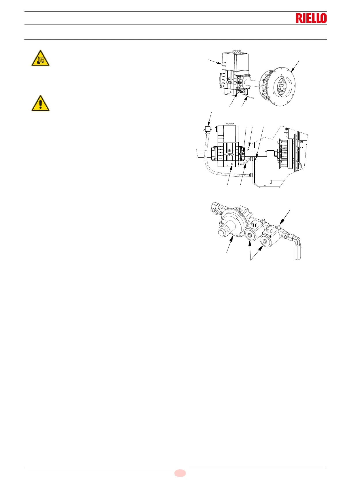
The compensation pipe 3)(Fig. 25) allows compensation to
occur for accidental blockage of the suction line due to a re-
duction in the gas delivered.
Key (Fig. 25)
1 Gas valve
2 Quick coupling
3 Compensation pipe (T)
4 Air/gas mixer in the circuit of the suction line
5 Electronic valve connection (XV1)
6 Maximum gas flow adjustment (V1)
7 Downstream pressure test point
8 Minimum gas flow adjustment (V2)
9 Metallic protective device
10 Pilot supply pressure
11 Pressure adjuster
12 Safety valves
Explosion danger due to fuel leaks in the pres-
ence of a flammable source.
Precautions: avoid knocking, attrition, sparks and
heat.
Make sure the fuel interception tap is closed be-
fore performing any operation on the burner.
The fuel supply line must be installed by qualified
personnel, in compliance with current standards
and laws.