57
20152192
Start-up, calibration and operation of the burner
7.7 Burner adjustment
The optimum adjustment of the burner requires an analysis of
flue gases at the generator outlet.
The burner application at the generator, the adjustment and the
testing must be carried out in compliance with the instruction
manual of the generator itself, including the control of the concen-
tration of CO and CO
2
in the flue gases and of their temperature.
Check in sequence:
– MAX output
– MIN output
The MAX output should be equal to the value requested by the
boiler used. To increase or decrease its value use the external
modulation control.
Measure the gas delivery on the counter to precisely establish the
burnt output.
Using a smoke analyser, measure the value of the CO
2
or the O
2
in order to optimise the burner calibration.
The correct values are: CO
2
8.2 - 9% (for methane).
To correct these values act on the gas valve in the following way:
to increase the gas delivery and the CO
2
: turn the V1 screw
towards the “+” sign (Fig. 168);
to reduce the gas delivery and the CO
2
: turn the V1 screw
towards the “-” sign (Fig. 168);.
The MIN output should be equal to the value requested by the
boiler used. To increase or decrease its value use the external
modulation control.
Measure the gas delivery on the counter to precisely establish the
burnt output (to be adjusted depending on gas pressure).
Using a smoke analyser, measure the value of the CO
2
or the O
2
in order to optimise the burner calibration.
The correct values are: CO
2
7.8 - 8.5% (for methane).
To correct these values act on the gas valve in the following way:
to increase the gas delivery and the CO
2
: turn the V2 screw
towards the “+” sign;
to reduce the gas delivery and the CO
2
: turn the V2 screw
towards the “-” sign;.
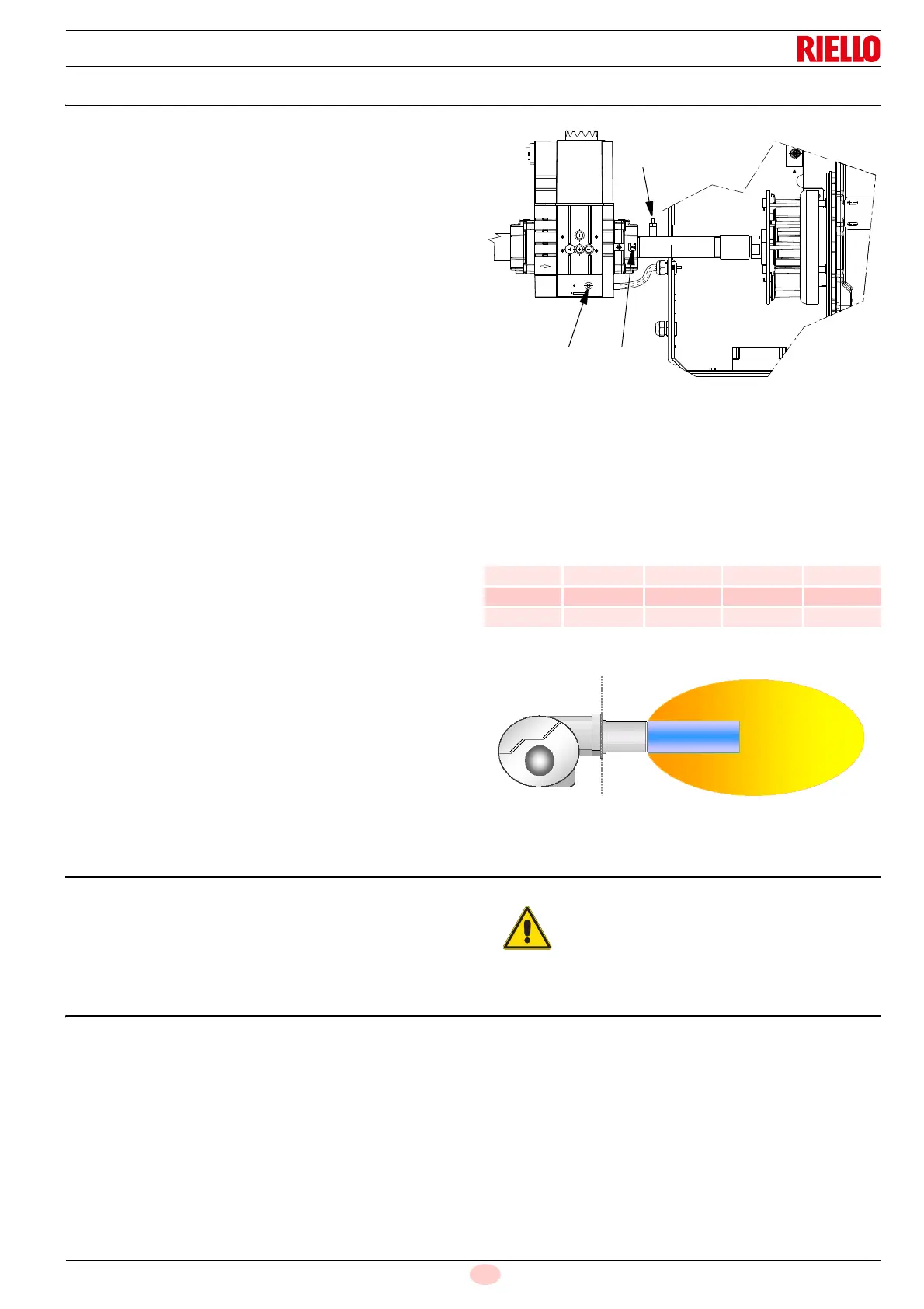
Key (Fig. 168)
1 Maximum gas flow adjustment (V1)
2 Pressure point downstream
3 Minimum gas flow adjustment (V2)
7.7.1 Indicative calibration values
Tab. R
7.8 Switching off the burner
Turn the “ON/OFF” switch to “OFF” (Fig. 167 on page 54).
Disable the electrical supply. If the burner is off for long periods,
close the manual gas gates.
7.9 Load controller inputs
Selecting the default output analogue source/phases input
with 3 positions (P654)
The following input signals can be selected and managed using
the parameter P654.
• 3 positions phase input (ASZxx.3x feedback potentiometer
necessary/depending on the sequence of the program)
• 0...10 V
• 0...135
• 0...20mA
• 4...20 mA with lockout at I <4 mA (AZL2...: Loc: 60)
For the connections, see the wiring diagrams.
MIN output MAX output
CO
2
(%) O
2
(%) CO
2
(%) O
2
(%)
Methane 8 6.6 8.5 5.7
LPG 9.5 6.4 10 5.6
G25 7.8 6.8 8.3 5.8
Turning the “ON/OFF” switch to “OFF” position
during the burner post-ventilation phase, the
equipment shuts down after a few seconds (ER-
ROR LOC:83).