20152192
26
Installation
5.6 Securing the burner to the boiler
5.6.1 Standard head version
The burners are supplied with the combustion head and elec-
trodes unital ready assembled.
Fasten main train unit 20)(Fig. 22) to mixer 18)(Fig. 22) by
means of supplied tube 26)(Fig. 22).
Insert the pilot train 27)(Fig. 23) on connector 28)(Fig. 23)
and tighten the nut fully home.
Check that the sealing ogive is inside the connector.
Fasten pilot train 27)(Fig. 23) with screws 29)(Fig. 23).
Tighten the studs 2)(Fig. 24) to the plate 1)(Fig. 24).
Position the refractory gasket 3)(Fig. 24).
Fix the flange 5)(Fig. 24) to the boiler plate and tighten the
nuts 4)(Fig. 24).
During this operation, take care not to touch the electrode
unit.
Provide an adequate lifting system.
The seal between burner and boiler must be air-
tight.
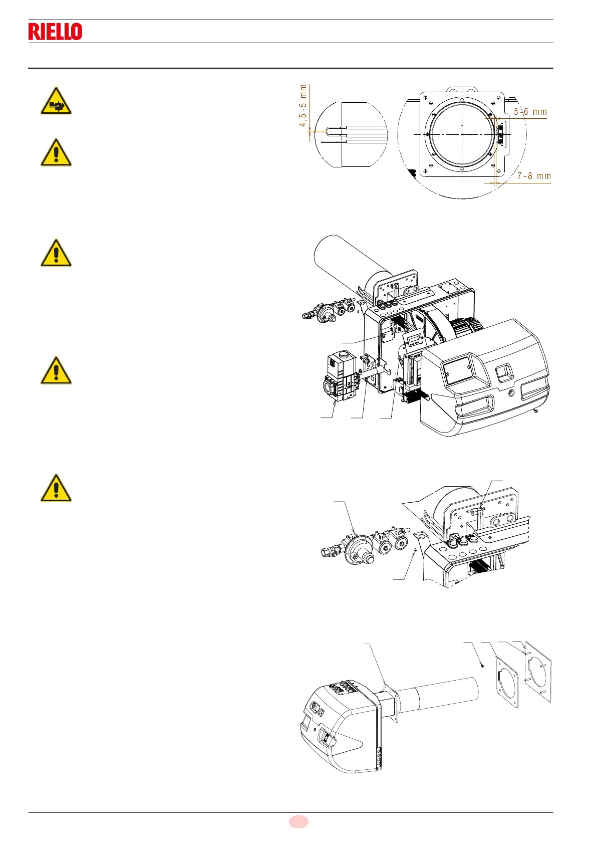
Before installing the burner on the boiler, make
sure the probe and electrodes are positioned cor-
rectly as in Fig. 21.
Use a suitable sealant and check the general gas
seal during operation, in particular with respect to
tube 26)(Fig. 22) and connector 28)(Fig. 23).
The seal of the burner-boiler and electrode unit
must be hermetic.