20152192
10
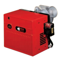
Technical description of the burner
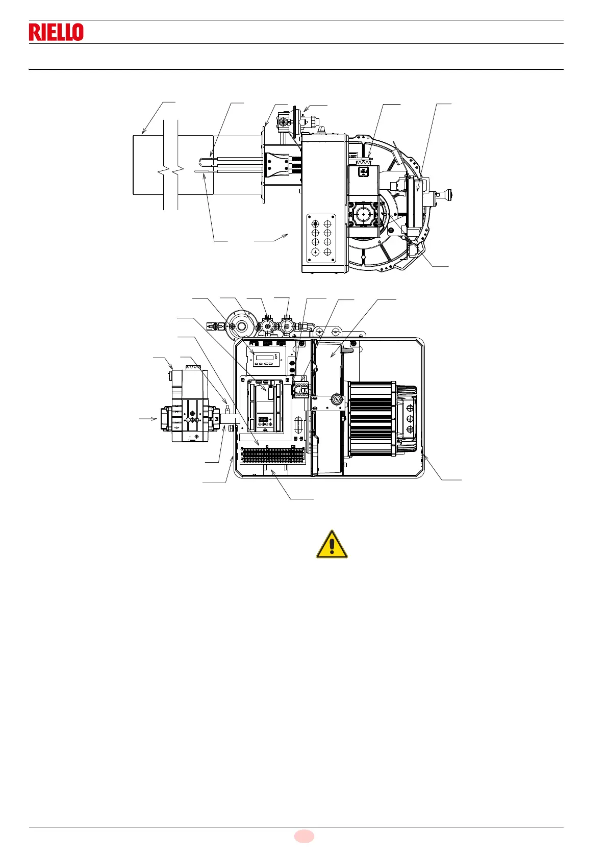
4.7 Burner description
1 Combustion head
2 Ignition electrode
3 Flame sensor probe
4 Gas valve
5 Air/gas mixer in the suction line circuit
6 Gas pressure test point
7 Gas valve pipe
8 Gas input
9 Boiler fixing flange
10 Fan
11 Air passage in fan
12 Electrical control box
13 Luminous push-button for reset
14 Plug-socket on ionisation probe cable
15 Terminal board for electrical wiring
16 Transformer
17 Plate with 4 holes, useful for passing electric cables
18 Fuses
19 Programming card
20 ON/OFF selector
21 Light signalling of mains live state
22 Three-phase contactor fan/output relay
23 Display
24 Pilot gas train
19
4
8
7
16
17
17
21
20
23
13
10
22
15
6
1
2
3
9
14
12
5
11
24
18
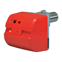
Burner lockout may occur.
CONTROL BOX LOCKOUT:
if the button 13) lights up (Fig. 2) it signals that the
burner is in lockout.
Press the push button to reset.