18
INSTALLATION
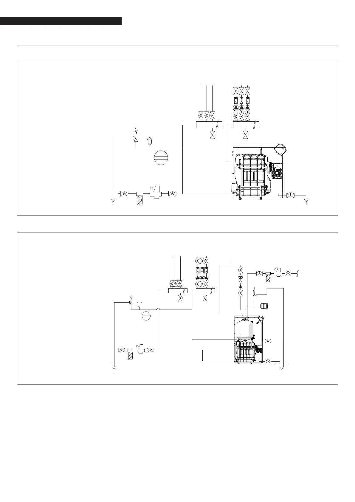
2.7 Typical water system schematics
Typical schematic - Central heating system - GITRÈ
1 Boiler
2 Central heating system man-
ifolds
3 Disconnect valves
4 Pumps
5 Non-return valves
6 Automatic vent valve
7 Boiler safety valve
8 Boiler drain cock
9 System lling cock
10 Water softener lter
11 CH expansion vessel
8
1
HEATING
RETURN
HEATING
FLOW
39
11
10
6
3
3 3
3
4
5
3
2 2
7
3
Schematic diagram - central heating and domestic hot water production - GITRÈ B/100
1 Boiler
2 Central heating system man-
ifolds
3 Disconnect valves
4 Pumps
5 Non-return valves
6 Automatic vent valve
7 Boiler safety valve
8 Boiler drain cock
9 Storage cylinder safety valve
10 System lling cock
11 CH expansion vessel
12 Storage cylinder
13 Storage cylinder drain cock
14 DHW expansion vessel
15 Water softener lter
16 Pressure reducer
17 DHW recirculation pump
8
13
12
HEATING
RETURN
HEATING
FLOW
DHW USER
3
3
3
3
3
17
5
3
9
14
3
1
15 16 3
4
5
3
2
7
6
11
310153
9
The DHW and central heating circuits must incorporate expansion vessels of adequate capacity as well as suitably rated safety
valves. The condensate drain must be connected to a suitable collection and drain system.
9
The choice of system components and the method of their installation are left up to the heating engineer installing the system.
Installers must use their expertise to ensure proper installation and functioning in conformity to all applicable legislation.
9
If needed, water supplies and recovery circuits must be conditioned by suitable treatment systems. Refer to the values listed in
the table on page 22.
0
Never run the boiler or the pumps dry.