32
COMMISSIONING AND MAINTENANCE
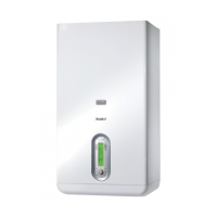
Provided all the above conditions are satised, start the boiler
up again, then analyse the combustion fumes.
The sampling hole for ue gas analysis must be located along
the straight section of ue at a distance (L) from the boiler ex-
haust. (Refer to applicable standards before drilling).
L
≥5°
9
Always plug the sampling hole after analysing the ue gas-
es.
3.3.1 Storage cylinder pump control
The pump is congured in the factory for a maximum head of 7
metres. Use the button (1) only to activate the button lock func-
tion as instructed below.
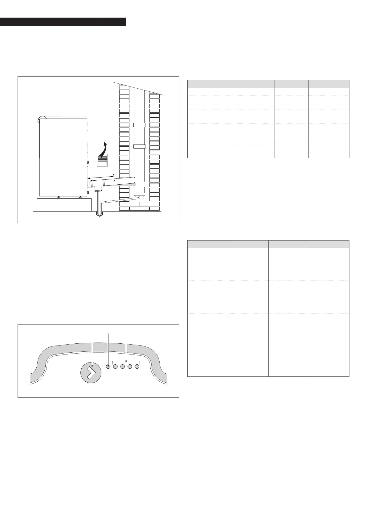
USER INTERFACE
The user interface consists of a push-button (1), a red/green LED
(2) and four yellow LEDs (3).
1 2 3
LED 1
LED 2
LED 3
LED 4
LED 5
FUNCTIONING MODE
Performance display
When the pump is running, LED 1 is green. The four yellow LEDs
indicate the pump's instantaneous electrical power consump-
tion as shown in the table.
Nr. displayed Meaning % power
LED 1 ashing green Stand-by 0
LED 1 green and LED 2 yellow,
both lit
Low load 0-25
LED 1 green and LEDs 2, 3 yellow,
all lit
Low-medi-
um load
25-50
LED 1 green, LEDs 2, 3, 4 yellow,
all lit
Medi-
um-high
load
50-75
LED 1 green, LEDs 2, 3, 4, 5 yellow,
all lit
High load 75-100
The pump functions at xed speed.
Alarm display
If the pump detects one or more alarm conditions, LED 1 changes
from green to red. When an alarm is active, the LEDs indicate
the type of alarm as shown in the following table. If more than
one alarm is active at the same time, the LEDs only show the
alarm condition with the highest priority. Alarm priority follows
the order of the table.
When no alarm is active, the user interface automatically dis-
plays pump performance.
Nr. displayed Meaning Function Action
LED 1 red and
LED 5 yellow,
both lit
The pump ro-
tor is blocked
The pump
automatically
attempts to
start every 1.5
seconds
Wait or check
that the
pump rotor is
free to rotate
LED 1 red and
LED 4 yellow,
both lit
Supply voltage
too low
Indica-
tion only.
The pump
continues to
function
Check the
voltage of the
power supply
LED 1 red and
LED 3 yellow,
both lit
Electronic
controller
error
The pump has
stopped be-
cause supply
voltage is too
low or be-
cause an error
has occurred
in the internal
electronic
controller
Check the
voltage of the
power supply
or replace the
pump
Button lock/unlock function
The button lock function serves to prevent improper use or acci-
dental changes to pump settings.
When the button lock is active, pressing the button has no ef-
fect. This prevents users from accidentally accessing setting
mode while allowing them to use setting display mode.
When the button is held down for 10 seconds, all the LEDs except
the red LED ash for one second to indicate that the button lock
function has been activated/deactivated.