24
INSTALLATION
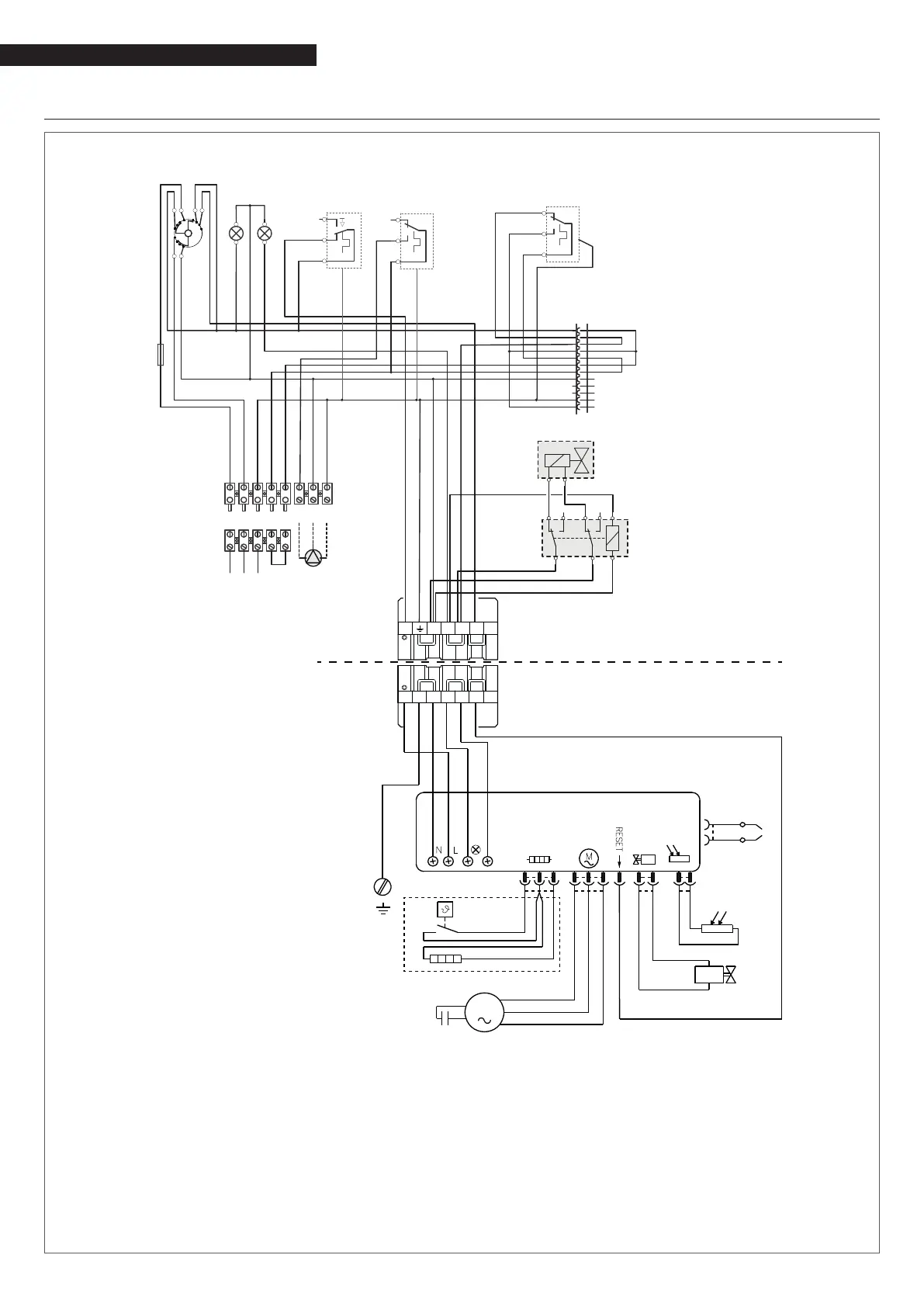
2.11 Wiring diagram
GITRÈ 4
LV
1
2
3
4
5
6
7
8
9
10
11
12
CO1
LR
2
1
C
TR
C3
A 1
B
2
CO1A
L1 N PE TA TA LPI NPI PE
PI
2
1
C
TS
2
1
C
Tm
MO1
L N PE
AE
230V ~ 50Hz
RE
DAI
C C
NC
1
2
N
N
NC
321NL1
TB
X6
XP6
MV
M
V
F
E
White
Yellow/Green
Black
Grey
Violet
HEAT
REQUESTA
Black
White
Blue
K
R
Red
BURNER CONTROLLER
AE Power supply
COM.G. 3 position function selector
LV Mains power indicator
LR Burner lockout indicator
TS Safety thermostat (110°C 0/-6) (*)
TR Boiler control thermostat (55 -
82°C) (*)
Tm Minimum temperature thermostat
(50°C) (*)
FU Mains power fuse 6.3 A-T
CO1-CO1A Multi-connectors
MO1 Terminal strip
PI Central heating pump (not
supplied)
DAI Automatic shut-off device (not
supplied; only where required).
The automatic shut-off device (DAI)
and the relay (RE) must be suitable
for a 230 VAC power supply.
RE Relay (not supplied)
X6 6 pin burner connector (female)
(*) Homologated
C Condenser
E Ignition electrodes
F Flame detector
K Thermostat for enabling start-up after pre-heating
MV Fan motor
R Heating element
TB Burner ground
V Fuel oil valve
XP6 6 pin burner connector (male)