28
INSTALLATION
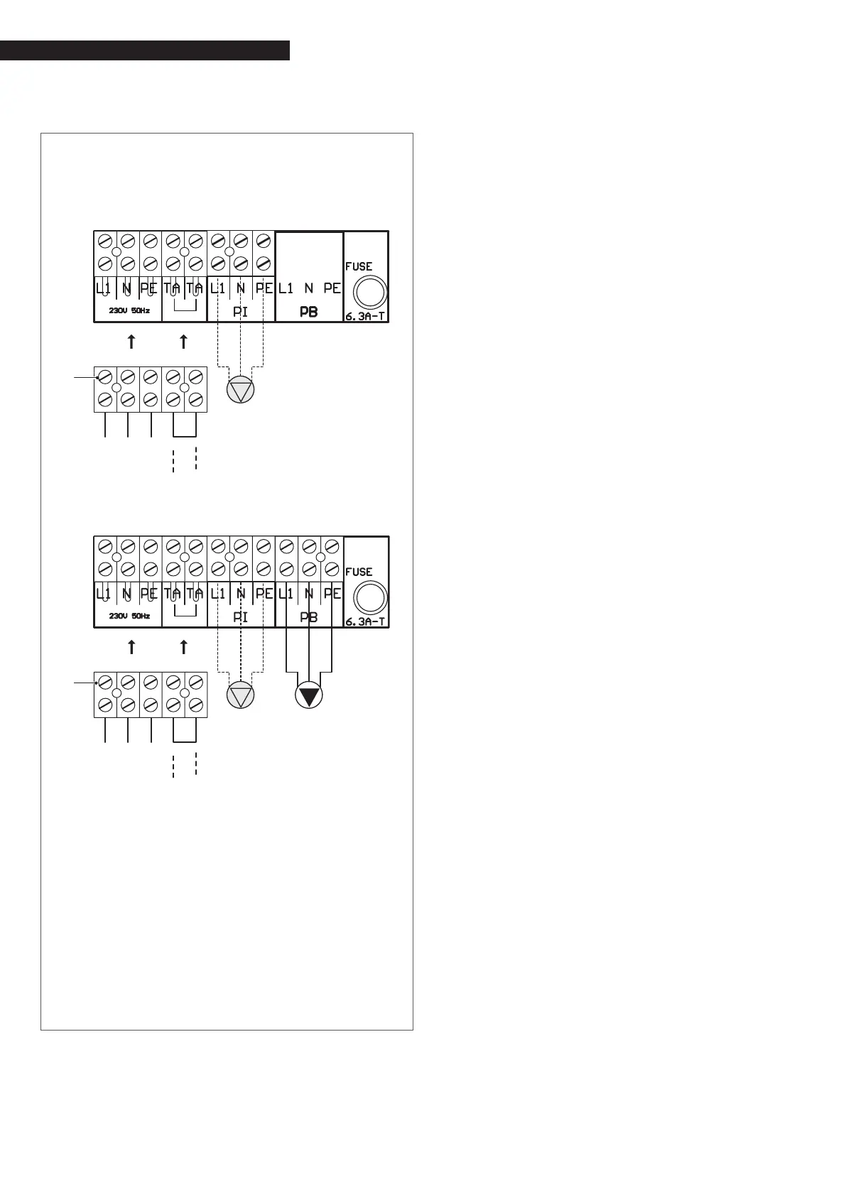
− Make the electrical connections as shown in the follow-
ing diagrams;
Connections to be made by the heating engineer – control
panel terminal strip
GITRÈ
6 7 8 9 10 11
L1 PE
TA
TA
1 2 3 4 5
N
L1 PE TA TA
1 2 3 4 5
N
L1 PEN
L1 PE
1 2 3
N
PI
230V 50Hz
GITRÈ B/100
67 8910 11
L1 PE
TA
TA
12345
N
L1 PE TA TA
12345
N
L1 PEN
L1 PE
123
N
PI
230V 50Hz
PB
123
L1 Live
N Neutral
PE Earth/ground
TA Room thermostat
PI Central heating pump (not supplied)
PB Storage cylinder pump
9
The jumper (TA-TA) must be removed from the terminal
strip (H) in order to connect up the room thermostat.
NOTE The room thermostat connection must be dry (no
voltage).
On completion of the electrical connections, replace all removed
components in the opposite order.
9
The following is mandatory:
− The use of an omnipolar magnetothermic switch, line
disconnecting switch in compliance with CEI-EN stand-
ards (contact opening of at least 3 mm)
− Respect the connection L (line) - N (neutral). Keep the
earth conductor 2 cm longer than the power supply con-
ductors
− Use cables with a section greater than or equal to 1.5
mm
2
, complete with cable terminal caps
− Refer to the wiring diagrams in this manual for all electric
operations
− Connect the equipment to an effective earthing system.
0
It is strictly forbidden to use water pipes to ground the ap-
pliance.
0
It is prohibited to pass the power supply and room thermo-
stat cables near hot surfaces (delivery pipes). If contact is
possible with parts that have temperatures above 50°C, use
a suitable type of cable.
The manufacturer is not responsible for any damage caused by
failure to earth connect the device and failure to comply with
what is indicated in the wiring diagrams.