RIGOL
© Copyright RIGOL Technologies, Inc. 2007. 1-21
User Manual for DM3000 Series
To Test Continuity
In view of Continuity measurement function, the following part demonstrated how to
link the measurement connection and how to choose measurement functions. The
following practice will gradually guide you to be familiar with the Continuity
measurement technique.
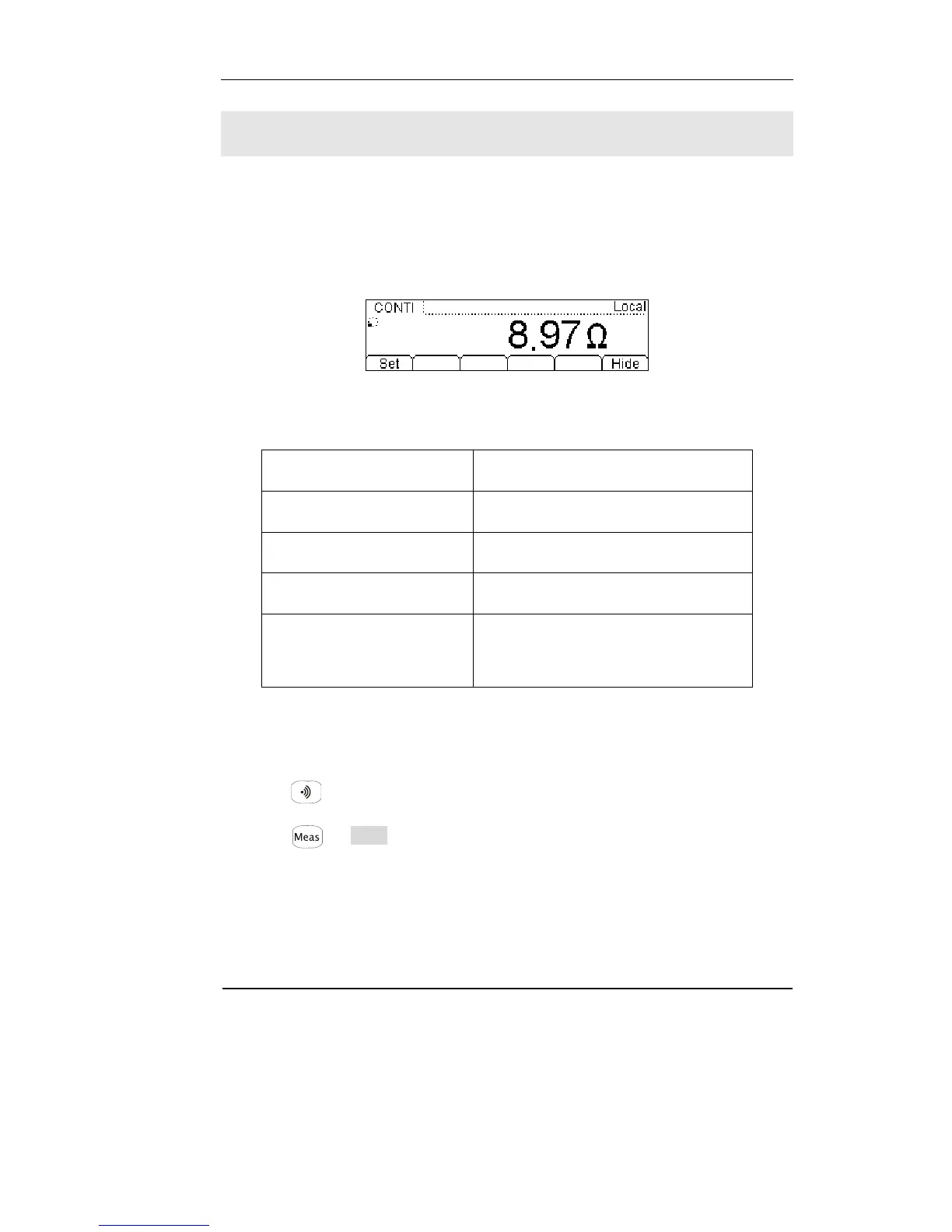
Figure 1-27
Table 1-8 Continuity measurement characteristics
Tests Current 1mA
Max Resolution Range fixed at 2KΩ
Open-circuit Voltage <5V
Import Protection 1000V (HI Terminal)
Configurable Parameters
0≤R
testing
≤Short-circuit impedance
(0Ω≤Short-circuit impedance≤2kΩ)
Basic measurement:
1. Connect test leads as Figure 1-28 shown. Red test lead connects the HI Terminal,
Black test lead connects the LO Terminal.
2. Press to select the Continuity Measurement
3. Setup the Short-circuit resistance.
Press Æ Res , to set up the Short-circuit Impedance. Default value of the
Short-circuit Impedance will be 10MΩ, this parameter had been setup, and the user
may carry on the Continuity measurement directly without modification.
 Loading...