EasyManuals Logo

Rockwell Automation Allen-Bradley AADvance T9110 Troubleshooting And Maintenance Manual

Rockwell Automation Allen-Bradley AADvance T9110
96 pages
To Next Page IconTo Next Page
To Previous Page IconTo Previous Page
Page #55 background imageLoading...
Page #55 background image
Rockwell Automation Publication ICSTT-RM406J-EN-P - February 2021 55
Chapter 6 Troubleshooting and Rectifying Channel/Field Faults
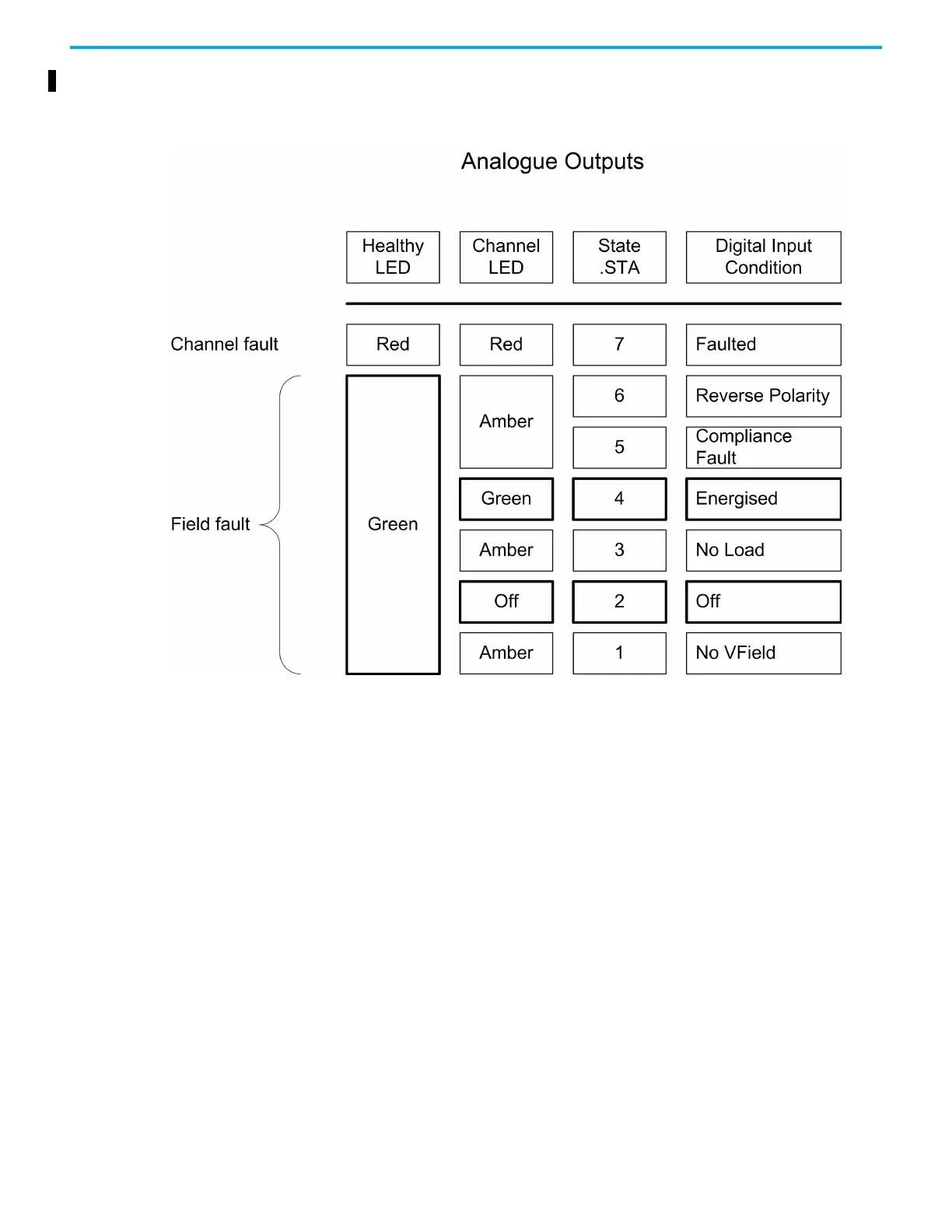
Correlation of Status Indicators with State Variable for an Analogue
Output
Start Troubleshooting
Channel/Field Faults
An investigation into a channel/field fault begins with a channel indication on
an I/O module showing amber. Do the following:
For digital input modules use chart 'A'.
For analogue input modules use chart 'B'.
For digital output modules use chart 'C'.
For analogue output modules use chart 'D'.
Use this circuit diagram in conjunction with chart 'A'.

Table of Contents

Other manuals for Rockwell Automation Allen-Bradley AADvance T9110

Questions and Answers:

Question and Answer IconNeed help?

Do you have a question about the Rockwell Automation Allen-Bradley AADvance T9110 and is the answer not in the manual?

Rockwell Automation Allen-Bradley AADvance T9110 Specifications

General IconGeneral
BrandRockwell Automation
ModelAllen-Bradley AADvance T9110
CategoryController
LanguageEnglish

Related product manuals