Rockwell Automation Publication ICSTT-RM406J-EN-P - February 2021 69
Chapter 6 Troubleshooting and Rectifying Channel/Field Faults
Installation
1. Examine the coding pegs on the termination assembly and make sure
that they fit the sockets on the rear of the new I/O module.
2. Place the I/O module on to the dowel pins on the T9300 I/O base unit.
Make sure the slot on the head of the module clamp screw is vertical and
then push the module home until the module connectors are fully mated
with the I/O base unit and termination assembly connectors.
3. The locking screw requires a quarter turn clockwise to lock. Use a broad
(9mm) flat blade screwdriver to lock the clamp screw. The locking screw
acts as a power interlock device and must be in the locked position when
power is applied otherwise the module will not be configured.
I/O Module Start-up
Process
The start-up sequence is different when a module is installed into an on-line
system that is running compared to installing the module into a system that is
off-line and has processor modules but no I/O modules installed.
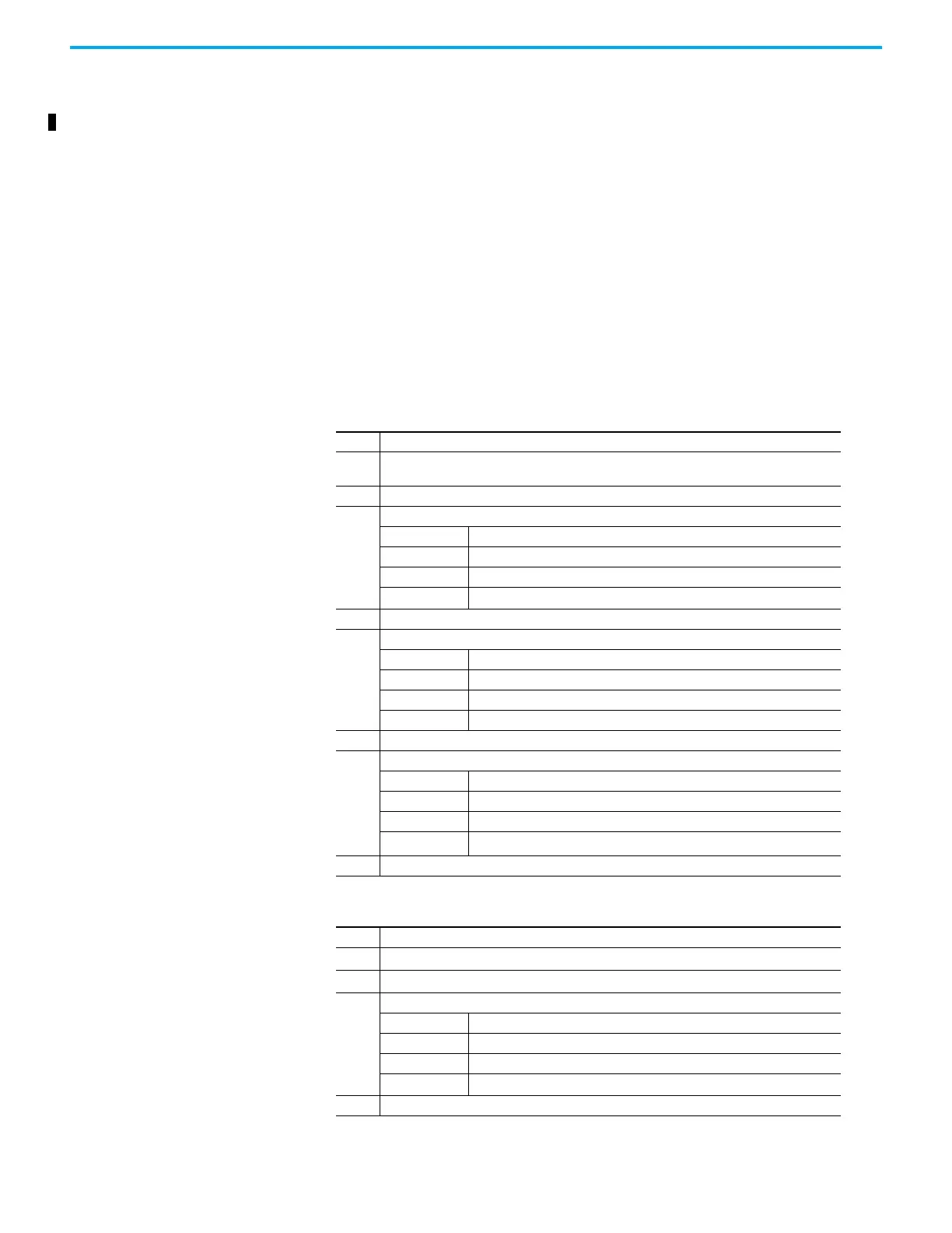
Table 6 - Single Module or First Module of a group Installation Procedure
Step Task
1.
This procedure applies to a single module installation or the first module of a redundant group
installation.
2 Install the I/O module and turn the locking screw to the lock position.
3.
The input module will show the following status indications:
Healthy GREEN
Ready RED
Run RED
Channel 1 – 8 Off
4. The input module will follow its start-up sequence and the module will educate.
5.
After approximately 3 seconds the module will now show the following status indications:
Healthy GREEN
Ready GREEN
Run AMBER
Channel 1 – 8 Off
6. Push the Fault Reset button on the processor module and the Run indication goes GREEN.
7.
The module will now be on-line with the following status indications:
Healthy GREEN
Ready GREEN
Run GREEN
Channel 1 – 8 Dependent on channel status
8. If the module fails to educate (and go on-line) replace the module.
Table 7 - Second or third Module of a Group Installation Procedure
Step Task
1. This procedure applies to a second or third module of a redundant group installation.
2 Install the Input/Output Module and turn the locking screw to the lock position.
3.
The module will provide the following status indications:
Healthy GREEN
Ready RED
Run RED
Channel 1 – 8 Off
4. The input module will follow its start-up sequence and the module will educate.

 Loading...


