Rockwell Automation Publication ICSTT-RM406J-EN-P - February 2021 43
Chapter 5 Troubleshooting and Rectifying Module Faults
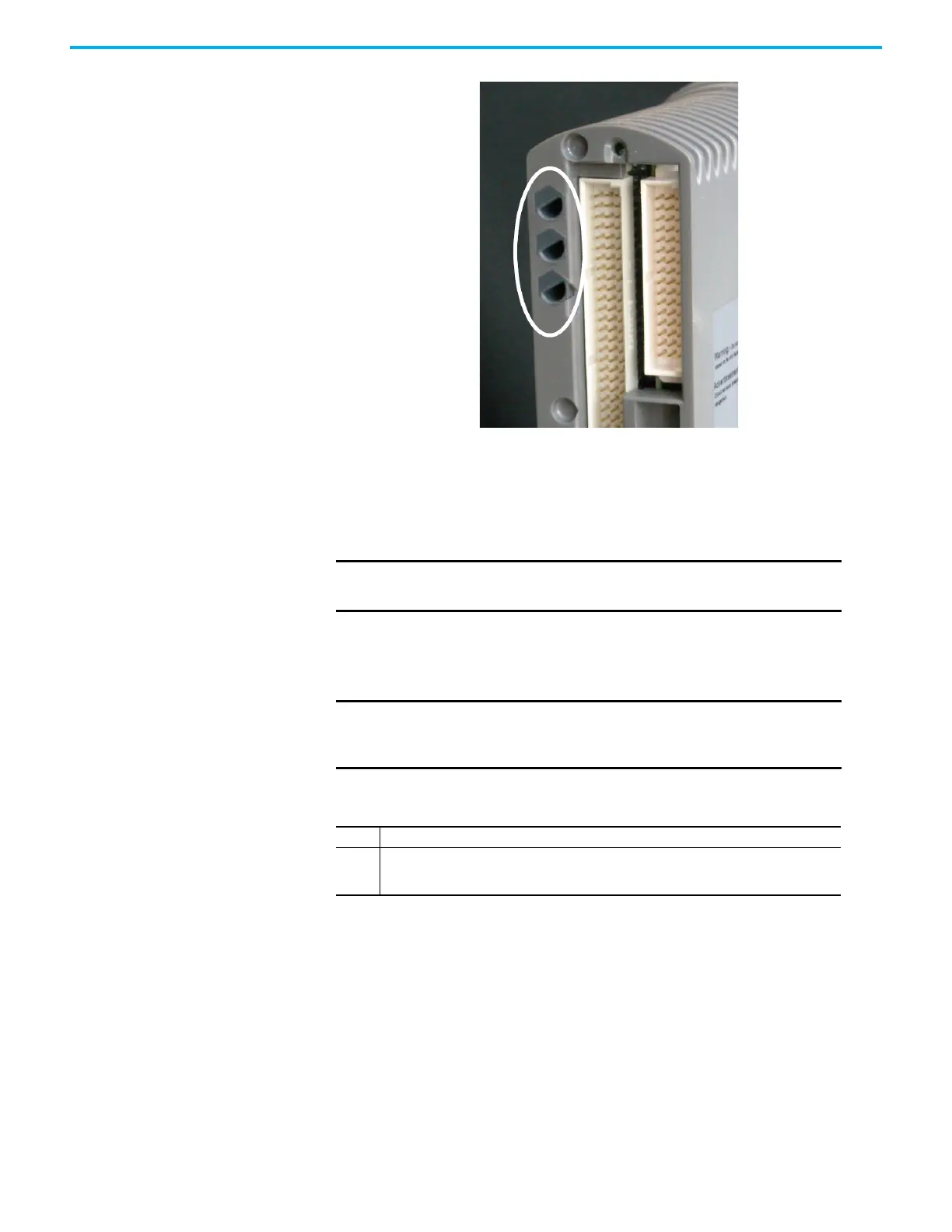
2. Place the processor module on to the coding pegs. Make sure the slot on
the head of the module locking screw is vertical and then push the
module home until the connectors are fully mated.
3. Using a broad (9mm) flat blade screwdriver turn the module locking
screw clockwise to lock.
Processor Module Start Up Process
NOTE The locking screw acts as a power interlock device and must be
locked or the module will not boot up.
NOTE When inserting more than one processor module they MUST be
inserted one at a time and the module be allowed to educate (in
the case of a 2nd and 3rd processor).
Table 4 - Single Processor Module Installation Procedure (New Processor Module)
Step Task
1.
With the power switched on place the processor module into slot A on the Base Unit
connectors and push the module home until the connectors are fully mated. Turn the
locking screw and lock the module in position.

 Loading...


