74 Rockwell Automation Publication 2198-UM005C-EN-P - February 2022
Chapter 5 Connect the Kinetix 5300 Drive System
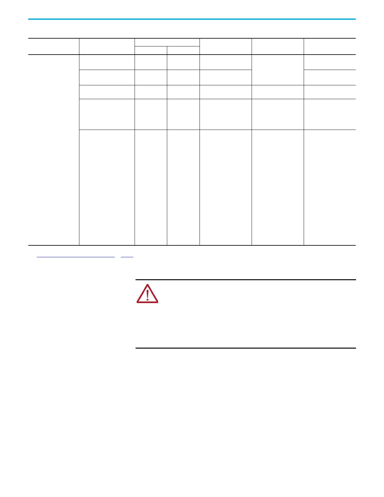
Table 35 - 24V and Brake Power, Shunt, Safety, and I/O Wiring Requirements
Kinetix 5300 Drive
Cat. No.
Description
Connects to Terminals
Wire Size
mm
2
(AWG)
Strip Length
mm (in.)
Torque Value
N•m (lb•in)
Pin Signal
2198-Cxxxx-ERS
PELV 24V power
(1)
(single-axis connector)
1
2
24V+
24V-
0.2…2.5
(24…12)
7.0 (0.28)
0.5…0.6
(4.4…5.3)
Brake power
1
2
MBRK+
MBRK-
0.14…1.5
(2)
(28…16)
0.22…0.25
(1.9…2.2)
Shunt resistor
—
—
DC+
SH
0.2…2.5
(24…12)
8.0 (0.31)
0.5…0.6
(4.4…5.3)
Safety
ST0-1/6
ST0-2/7
ST0-3/8
ST0-4/9
ST0-5/10
SB+
SB-
S1
SC
S2
0.2…1.5
(24…16)
10.0 (0.39)
—
(3)
Digital inputs and
Auxiliary feedback
1
2
3
4
5
6
7
8
9
10
11
12
13
14
15
16
17
18
19
20
IN1
COM
IN2
COM
Shield
AUX_AM+
AUX_BM+
AUX_IM+
AUX_EPWR_5V
Shield
IN3
COM
IN4
COM
Shield
AUX_AM-
AUX_BM-
AUX_IM-
AUX_COM
Shield
0.2…1.5
(24…16)
10.0 (0.39)
—
(3)
(1) The wire size, strip length, and torque specifications shown here apply to the single-axis connector that ships with the drive. For the shared-bus connector specifications, refer to
Shared-bus 24V Connector Wiring Specifications
on page 76.
(2) Motor brake wires are part of the Kinetix 2090 motor cable.
(3) This connector uses spring tension to hold wires in place.
ATTENTION: To avoid personal injury and/or equipment damage, observe the
following:
• Make sure installation complies with specifications regarding wire types,
conductor sizes, branch circuit protection, and disconnect devices. The National
Electrical Code (NEC) and local codes outline provisions for safely installing
electrical equipment.
• Use motor power connectors for connection purposes only. Do not use them to
turn the unit on and off.
• Ground shielded power cables to prevent potentially high voltages on the shield.

 Loading...


