Rockwell Automation Publication 7000L-UM301F-EN-P - March 2020 147
Operator Interface Chapter 3
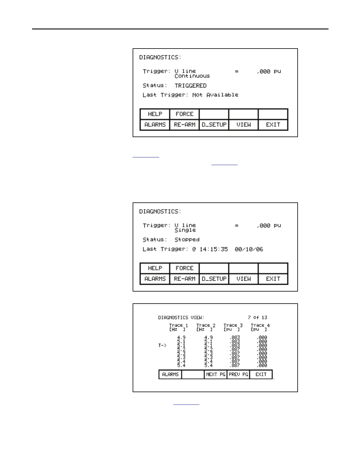
Figure 155 - Diagnostic Triggered
Once the data has started to be collected, the status will show 'triggered' as in
Figure 155
. When the buffer contains a complete capture, it will show “stopped”
(if a single capture), as shown in Figure 156
. The time and date at which the
trigger occurred is displayed. The trend buffers may only be viewed when their
status is ‘stopped’. If in continuous mode, the capture will stop when the buffers
are viewed. To view the trend buffers, press the [F9] key.
Figure 156 - Diagnostic Stopped
Figure 157 - View the Trend Buffer(s)
A screen such as Figure 157 will be shown. Upon initial entry, the screen will be
positioned to the trigger point, shown by the "T ->". To view data either side of
the trigger point, press the [F8] and [F9] keys.

 Loading...


